Panel module, driving circuit and display device

a technology of driving circuit and display device, applied in the field of panel modules, can solve problems such as the inability to quickly cope with a change of imag

Inactive Publication Date: 2011-05-05
FUJITSU LTD
View PDF6 Cites 3 Cited by
  • Summary
  • Abstract
  • Description
  • Claims
  • Application Information

AI Technical Summary

Benefits of technology

[0014]According to an aspect of an embodiment of the invention, a panel module includes a display element in which voltage is applied to a plurality of first electrodes arrayed on a substrate and a plurality of second electrodes arrayed in a direction different from a direction of the first electrodes, the display element changing a state of liquid crystal according to voltage of areas where the first electrodes and the second electrodes cross; an inverting unit that acquires polarity data indicating whether positive voltage is applied or negative voltage is applied to the first electrodes and the second electrodes and image data displayed on the display element and outputs, based on the polarity data, inverted image data or un-inverted image data; a first applying unit that selects one or more of the first electrodes corresponding to an area where the image data is displayed and applies, based on the polarity data, the positive voltage or the negative voltage to the selected one or more of the first electrodes; and a second applying unit that applies, based on the polarity data and the image data output from the inverting unit, the positive voltage and the negative voltage to the second electrodes.

Problems solved by technology

Therefore, in the method in which the common driver selects the first electrodes one by one and then applies voltage to the first electrodes to display image data in order, it is impossible to quickly cope with a change of an image.

Method used


Image

  • Panel module, driving circuit and display device
  • Panel module, driving circuit and display device
  • Panel module, driving circuit and display device

Examples


first embodiment

[a] First Embodiment

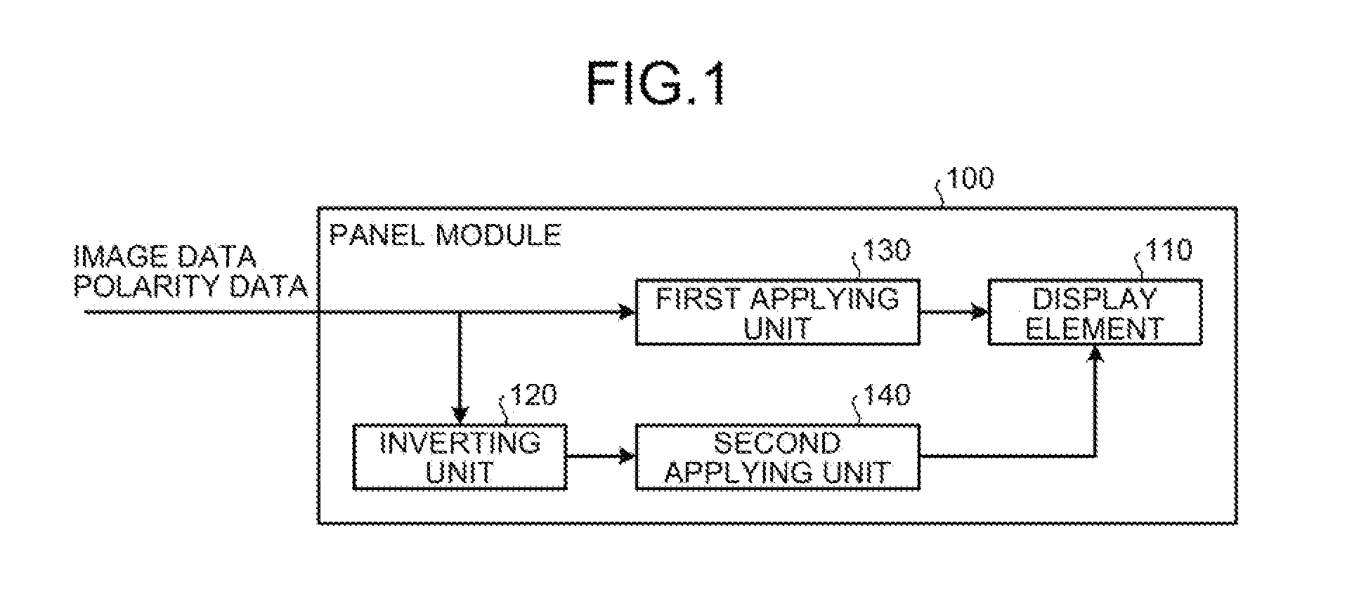
[0044]FIG. 1 is a diagram of the configuration of a panel module according to a first embodiment. As illustrated inFIG. 1, a panel module 100 includes a display element 110, an inverting unit 120, a first applying unit 130, and a second applying unit 140.

[0045]In the display element 110, voltage is applied to a plurality of first electrodes arrayed on a substrate and a plurality of second electrodes arrayed in a direction different from a direction of the array of the first electrodes. The display element 110 changes a state of liquid crystal depending on voltage in areas where the first electrodes and the second electrodes cross.

[0046]The inverting unit 120 acquires polarity data indicating whether positive voltage is applied to the first electrodes and the second electrodes or negative voltage is applied to the first electrodes and the second electrodes and image data displayed on the display element 110. The inverting unit 120 outputs, based on the polarity da...

second embodiment

[b] Second Embodiment

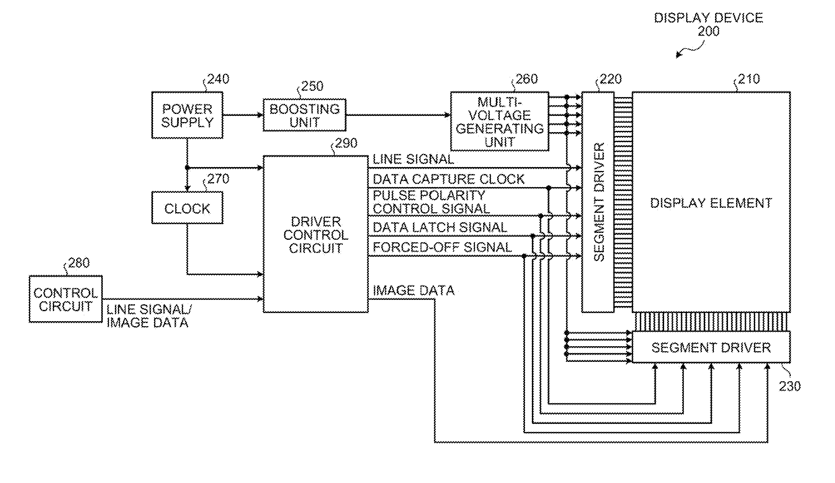
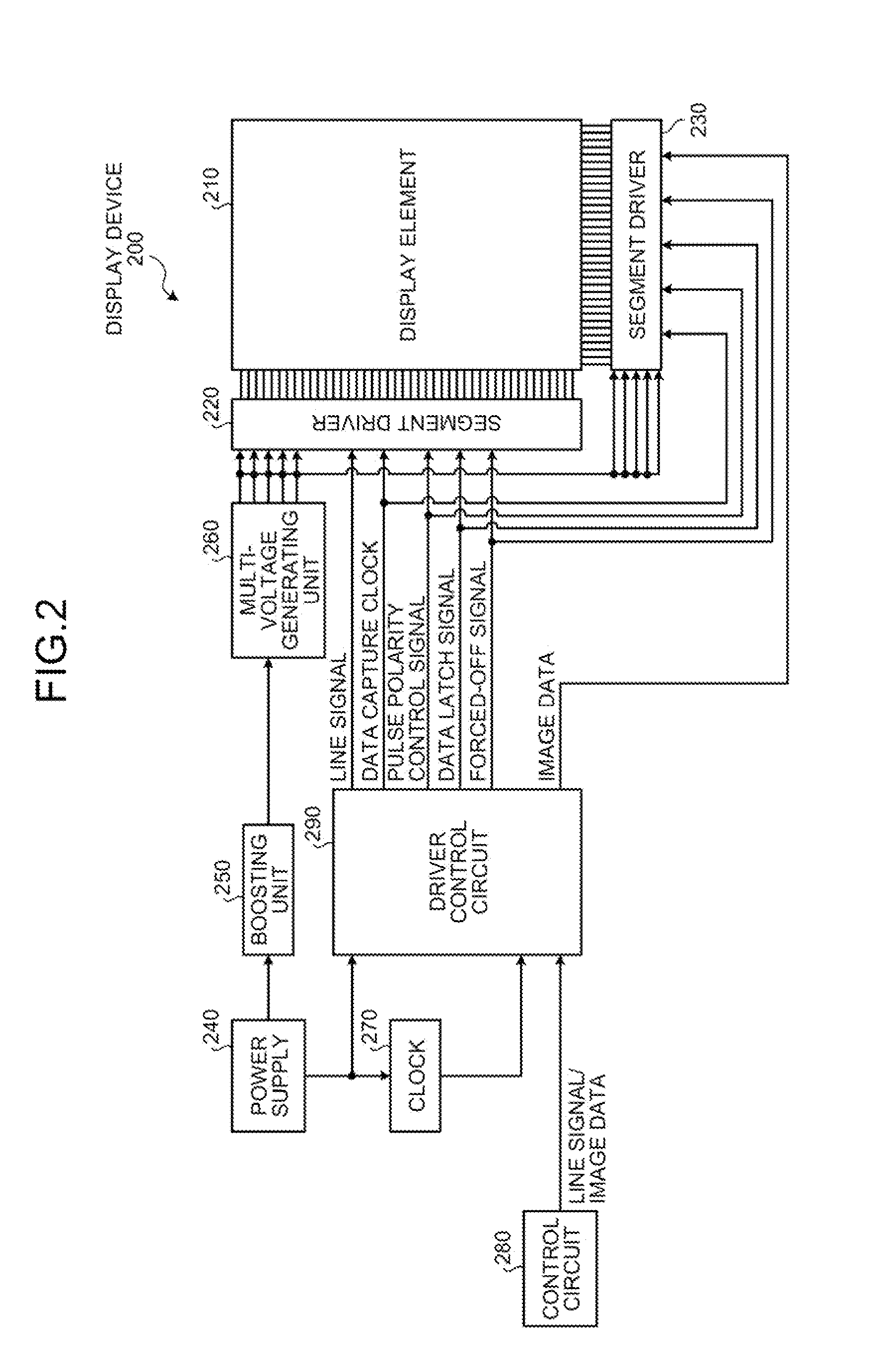
[0050]FIG. 2 is a diagram of the configuration of a display device according to a second embodiment. As illustrated in FIG. 2, a display device 200 includes a display element 210, segment drivers 220 and 230, a power supply 240, a boosting unit 250, a multi-voltage generating unit 260, a clock 270, a control circuit 280, and a driver control circuit 290.

[0051]The display element 210 is an element in which cholesteric liquid crystal is sandwiched by substrates. On the substrate of the display element, a plurality of electrodes are arrayed in a matrix form. When voltage is applied to the electrodes arrayed on the substrate, the voltage is transmitted to the cholesteric liquid crystal and a state of molecular of the cholesteric liquid crystal can be adjusted. In the following explanation, the electrodes in the horizontal direction arrayed on the substrate are referred to as first electrodes; the electrodes in the vertical direction are referred to as second electro...


PUM

PropertyMeasurementUnit
voltageaaaaaaaaaa
voltageaaaaaaaaaa
voltageaaaaaaaaaa

Abstract

A display device selects one or more of first electrodes corresponding to image data using a general-purpose segment driver and applies predetermined voltages respectively to the first electrodes of selection targets and non-selection targets. A driver control circuit outputs, according to a pulse polarity control signal, inverted image data or un-inverted image data to a segment driver. The segment driver applies voltage to second electrodes based on the image data acquired from the driver control circuit.

Description

CROSS-REFERENCE TO RELATED APPLICATION[0001]This application is based upon and claims the benefit of priority of the prior Japanese Patent Application No. 2009-225078, filed on Sep. 29, 2009, the entire contents of which are incorporated herein by reference.FIELD[0002]The embodiments discussed herein are directed to a panel module and the like.BACKGROUND[0003]In recent years, development of a display device using cholesteric liquid crystal (also referred to as chiral nematic liquid crystal) is in progress. FIG. 23 is a diagram of the structure of the cholesteric liquid crystal. As illustrated in FIG. 23, the cholesteric liquid crystal is sandwiched by two substrates. Electrodes are arrayed on the substrates in a matrix form. The substrates and the cholesteric liquid crystal are collectively referred to as a display element. The state of the cholesteric liquid crystal changes based on a voltage applied to the display element adjusted by the display device. Specifically, the state of ...

Claims


Application Information

Patent Timeline
Patent Type & Authority Applications(United States)
IPC IPC(8): G02F1/133G06F3/038
CPCG09G3/2092G09G3/3614G09G3/3629G09G3/3692G09G2370/08G09G2310/021G09G2310/0291G09G2310/08G09G3/3696
Inventor UEHARA, HIROKATA
Owner FUJITSU LTD
Why Eureka
Try Eureka