Thermochromic Filters and Stopband Filters for Use with Same

a technology of stopband filter and filter, which is applied in the direction of optics, instruments, optical elements, etc., can solve the problems of increasing the difficulty of extending the band edge deep into the infrared, and the benefits of doing so are increasingly sparse, so as to improve the building energy savings associated with improve the energy throughput and operating temperature of the dynamic optical material or devi

Inactive Publication Date: 2011-05-05
RAVENBRICK
View PDF139 Cites 46 Cited by
  • Summary
  • Abstract
  • Description
  • Claims
  • Application Information

AI Technical Summary

Benefits of technology

[0013]In yet another exemplary implementation, an optical or infrared stopband filter attenuates solar energy that occurs outside a band edge of a dynamic optical material or device. The stopband filter has a reflective or absorptive property that is mildly attenuating or non-attenuating across a functional bandwidth of the dynamic optical material or device and a reflective or absorptive property that is strongly att

Problems solved by technology

In addition, while it may seem desirable to extend the band edge of a dynamic building material to cover the entire solar spectrum, in practice it becomes increasingly difficult to extend the ban

Method used


Image

  • Thermochromic Filters and Stopband Filters for Use with Same
  • Thermochromic Filters and Stopband Filters for Use with Same
  • Thermochromic Filters and Stopband Filters for Use with Same

Examples


Embodiment Construction

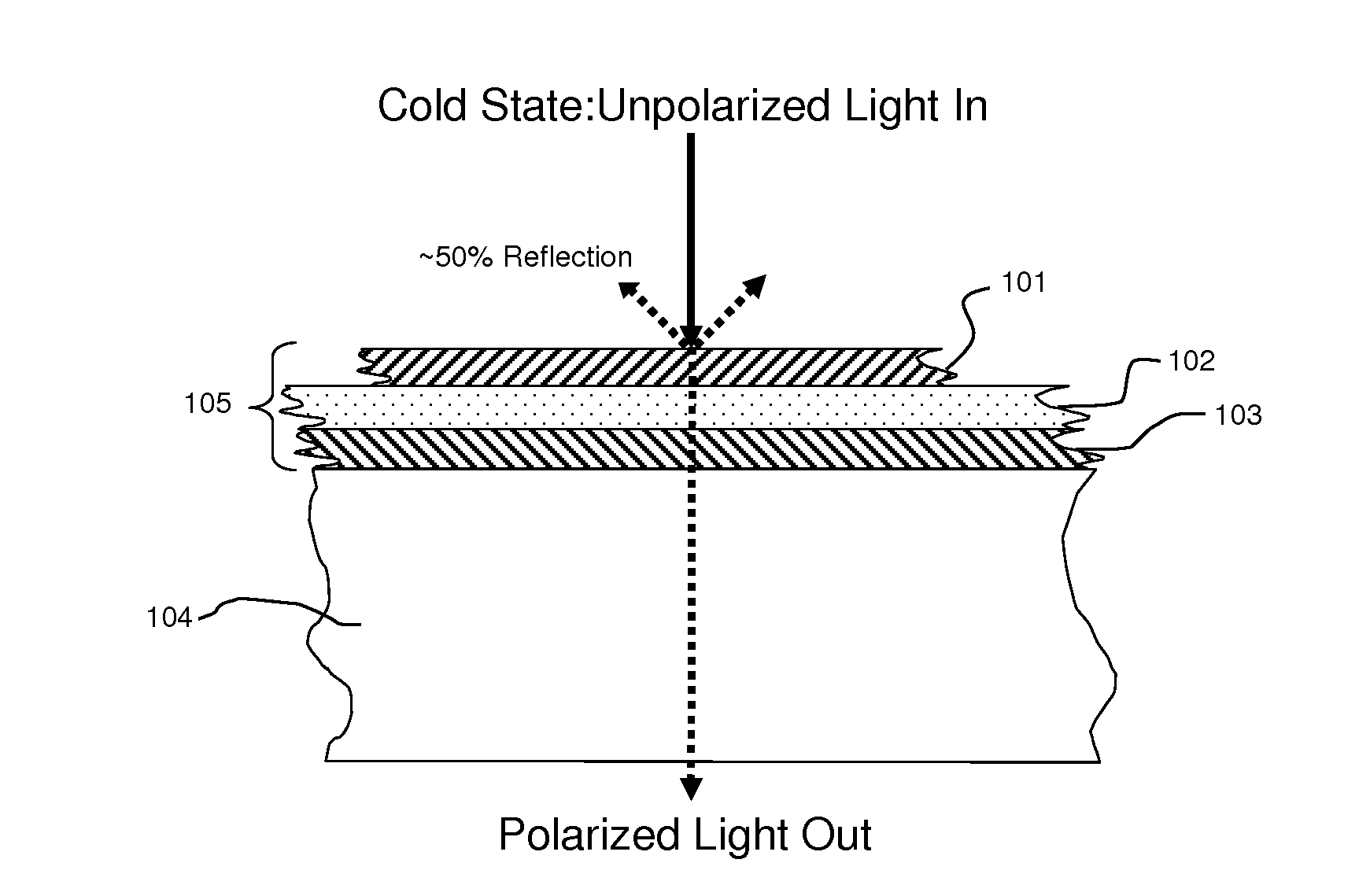
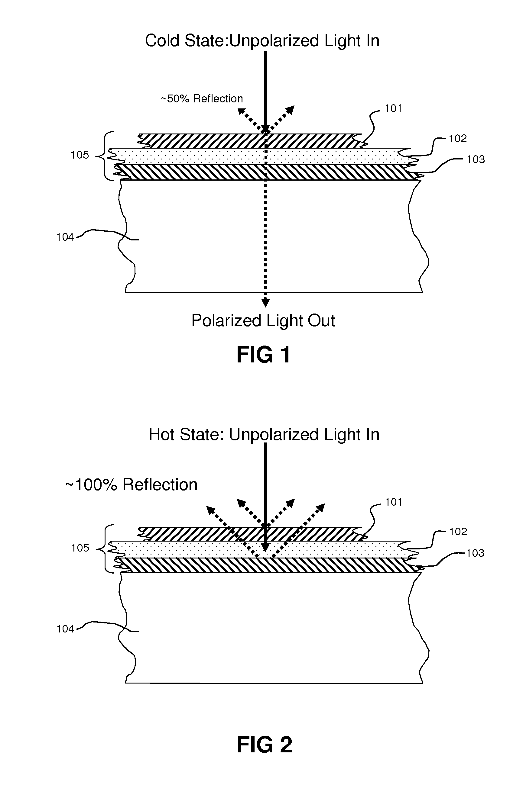
[0029]FIG. 1 is a schematic representation of an exemplary thermoreflective filter 105 laminated to a sheet of glass 104 in its cold or transparent state. The thermoreflective filter 105 is composed of an outer polarizer layer 101, and inner polarizer layer 103 with a polarity generally perpendicular to the outer polarizer 101, and a liquid crystal layer 102 with a low clearing point temperature between 0° C. and 40° C. When unpolarized light enters the device, it passes through the outer polarizer 101, where up to 50% of the light is reflected because it is of perpendicular polarity to the polarizer 101. The remaining light, with the same polarity as the polarizer, is transmitted through the twisted nematic liquid crystal layer 102, where its polarity is rotated by approximately 90 degrees to match the polarity of the inner polarizer 103. The light is therefore able to propagate through the inner polarizer 103 and thus approximately 50% of the incident light is able to pass through...


PUM


Abstract

Thermochromic filters use combinations of absorptive, reflective, thermoabsorptive, and thermoreflective elements covering different portions of the solar spectrum, to achieve different levels of energy savings, throw, shading, visible light transmission, and comfort. Embodiments include stopband filters in the near-infrared spectrum.

Description

CROSS REFERENCE TO RELATED APPLICATIONS[0001]This application claims the benefit of priority pursuant to 35 U.S.C. §119(e) of U.S. provisional patent application No. 61 / 256,853 entitled “Infrared stopband filter for use with thermochromic and electrochromic building materials” filed 30 Oct. 2009, which is hereby incorporated herein by reference in its entirety.[0002]This application is also related to the following: U.S. Pat. No. 7,768,693; U.S. Pat. No. 7,755,829; U.S. Patent Application Publication No. 2009 / 0167971; U.S. Patent Application Publication No. 2008 / 0210893; and U.S. Patent Application Publication No. 2009 / 0268273, the disclosures of each are hereby incorporated herein by reference in their entirety.BACKGROUND[0003]1. Technical Field[0004]The subject matter described herein relates to the design of devices for controlling the flow of light and radiant heat through selective reflection, transmission, and / or absorption and re-emission. The technology has particular, but n...

Claims


Application Information

Patent Timeline
IPC IPC(8): G02F1/01
CPCG02B5/23G02B5/208
Inventor MCCARTHY, WILPOWERS, RICHARD M.
Owner RAVENBRICK
Why Eureka
Try Eureka