Lens displacement mechanism using shaped memory alloy

a technology of shaped memory alloy and displacement mechanism, which is applied in the direction of printers, instruments, camera focusing arrangement, etc., can solve the problems of voice coil motor damage, cost is quite expensive, general piezoelectric material cannot endure high temperature of reflow process,

Inactive Publication Date: 2011-05-05
E PIN OPTICAL IND
View PDF5 Cites 44 Cited by
  • Summary
  • Abstract
  • Description
  • Claims
  • Application Information

AI Technical Summary

Benefits of technology

[0005]It is another object of the present invention to provide a lens displacement mechanism using shaped memory alloy that further includes a recovery spring element disposed on the lens. When the control current is cut off, the SMA wire is cooled and expanded back to original length. Then the recovery spring element provides the lens a recovery force that is opposite to a pulling force of the contracted SMA wire so as to drive the lens back to original place and auto focusing is achieved.
[0006]It is a further object of the present invention to provide a lens displacement mechanism using shaped memory alloy that includes a guide slot and a corresponding guide rail arranged between the lens and edges of a housing so as to make the lens move and slide stably inside the housing.

Problems solved by technology

However, the general piezoelectric material is unable to endure high temperature of a reflow process.
Once a special piezoelectric material that is durable to high temperature is used, the cost is quite expensive.
But, under high temperature of the reflow process, the voice coil motor may be damaged or the magnetic force is reduced.
Therefore, this leads to difficulty in mass production.
However, most of them have complicated design and large volume so that they can't match requirement of compact design of the lens modules.
Thus the movement and structure of the lens displacement mechanism are too complicated and this leads to negative effects on design requirements of compact lens module and low cost as well as has disadvantageous in mass production by SMT (Surface-Mount Technology).

Method used


Image

  • Lens displacement mechanism using shaped memory alloy
  • Lens displacement mechanism using shaped memory alloy
  • Lens displacement mechanism using shaped memory alloy

Examples


first embodiment

The First Embodiment

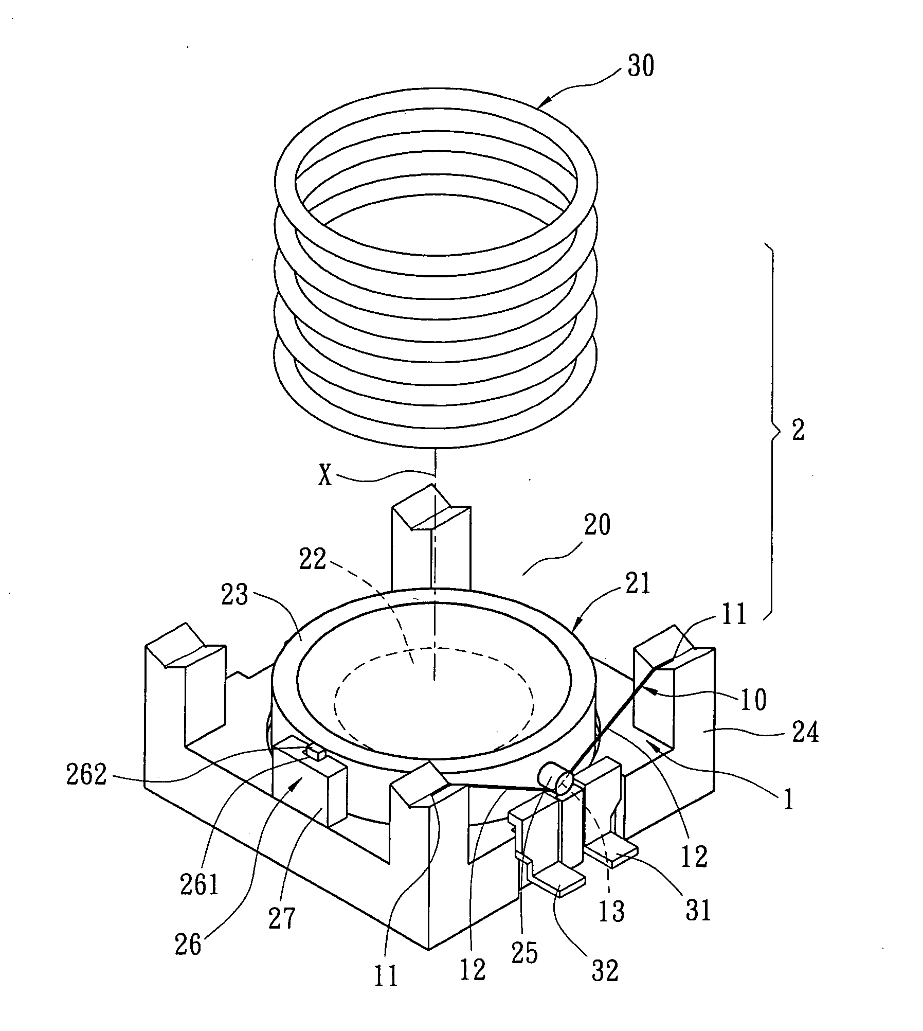
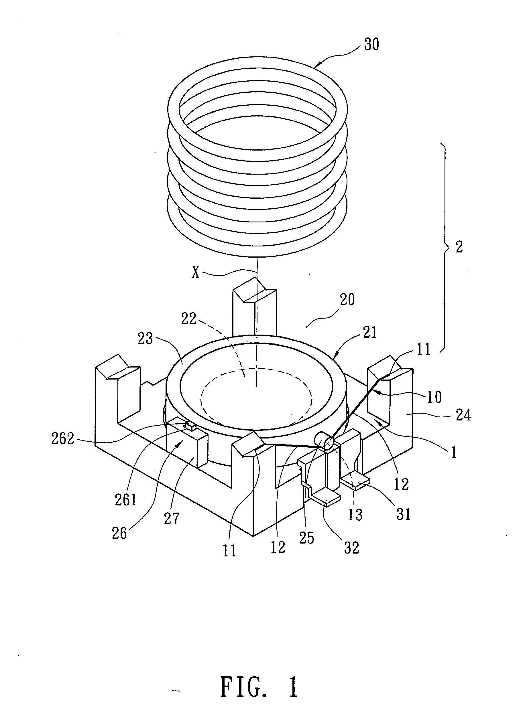
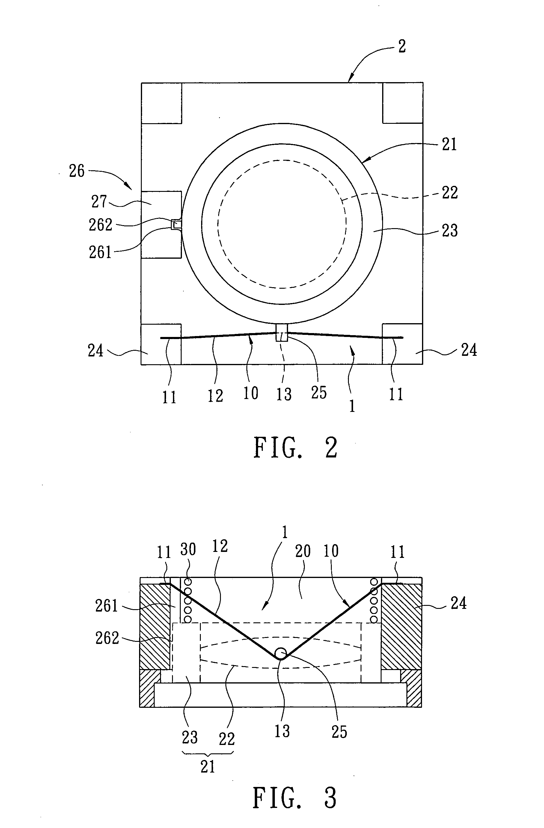
[0021]Refer from FIG. 1 to FIG. 3, one SMA wire 10 is used in this embodiment. When zooming from tele to wide, the lens 21 is moved away from the image side and towards the object side. While zooming, the lens 21 moves under control of a focus button (not shown in figure). When user presses the focus button, the lens displacement mechanism 1 gets control current passed from electrodes 31, 32. After a control current passing through the SMA wire 10, joule heat generates due to resistance of the SMA wire 10. Thus the SMA wire 10 is heated and contracted. Due to linear relationship among the length, temperature and the control current of the SMA wire 10, displacement of the lens 21 can be controlled according to contraction of the SMA wire 10. Thus the distance between the lens 21 and an image-forming plane is changed so as to achieve auto focusing. In this embodiment, the SMA wire 10 is made from Nickel-Titanium alloy with diameter of 0.002″. The distance change be...

second embodiment

The Second Embodiment

[0025]Refer from FIG. 4 to FIG. 6, this embodiment includes two SMA wires 10. The two SMA wires 10 are arranged symmetrically or in equal distance around the lens 21. The driving way and function of each SMA wire 10 is the same with that in the first embodiment. A recovery spring element 30 is disposed on the lens 21 for providing a recovery force in opposite direction to the pulling force of the contracted SMA wire 10 so as to turn the lens 21 back to a balance place.

[0026]Furthermore, a guide rail device 26 is disposed between the lens 21 and the housing 20. The guide rail device 26 is arranged on one side between the two SMA wires 10 so that the lens 21 moves and slides stably inside the housing 20 by the guide rail device 26.

[0027]Or two guide rail devices 26 are disposed between the lens 21 and the housing 20. The two guide rail devices 26 are arranged symmetrically in accordance with positions of the two SMA wires 10. As shown from FIG. 4 to FIG. 6, the tw...

third embodiment

The Third Embodiment

[0028]Refer from FIG. 7 to FIG. 9, this embodiment includes four SMA wires 10. The four SMA wires 10 are arranged symmetrically or in equal distance around the lens 21. For example, the SMA wires 10 respectively are arranged on four sides of the lens 21. The driving way and function of each SMA wire 10 is the same with that in the second embodiment. Moreover, a recovery spring element 30 is disposed on the lens 21 for providing a recovery force in opposite direction to the pulling force of the contracted SMA wire 10 so as to turn the lens 21 back to balance place.

[0029]In this embodiment, four SMA wires 10 respectively are disposed on four sides surrounding the lens 21 so as to provide the lens 21 equipollent contacting and pulling force. Thus the lens 21 moves stably inside the housing 20. Basically, there is no need to add the guide rail devices 26 in this embodiment. Furthermore, once an image quality feedback mechanism is added to control and regulate the fou...


PUM


Abstract

A lens displacement mechanism using shaped memory alloy (SMA) applied to an auto-focusing lens module is disclosed. The lens displacement mechanism comprising at least one SMA wire. Two opposite ends of the SMA wire are fixed and a longitudinal mid-point of an intermediate movable portion between the two opposite ends is tightened and is fixed on a corresponding hook disposed on an outer edge of the lens so that the intermediate movable portion is tightened between the two opposite ends. When the SMA wire is heated, the intermediate movable portion contracts to pull the hook of the lens for driving the lens to move and slide along with an optical axis so as to achieve auto-focus control. The present lens displacement mechanism is simple in structure and reflow process. Therefore, the present displacement mechanism is suitable to be used in portable camera or mobile phone or PDA, which needs to be small and have easily mass production by SMT.

Description

BACKGROUND OF THE INVENTION[0001]The present invention relates to a lens displacement mechanism using shaped memory alloy (SMA), especially to a lens displacement mechanism that uses SMA to control forward / backward movement of the lens for zooming and such mechanism is applied to an auto-focusing lens module.[0002]Portable electronic devices such as digital cameras, mobile phones with camera function, or notebooks available now are generally disposed with auto-focusing (AF) compact camera, so called with auto-focusing lens module inside. The auto-focusing lens module primarily consists of a housing, a lens and a lens displacement mechanism. The lens is consists of a lens holder and a lens group. The lens holder and the lens group are mounted in the housing. The lens displacement mechanism is used for driving the lens in moving along an optical axis or toward / away from an object side by sliding or screw rotation for auto-focus control. A conventional lens displacement mechanism is co...

Claims


Application Information

Patent Timeline
Patent Type & Authority Applications(United States)
IPC IPC(8): G02B7/02
CPCG02B7/08
Inventor SHYU, SAN-WOEIWU, SHR-BINHUANG, CHIH-HSIUNG
Owner E PIN OPTICAL IND
Why Eureka
Try Eureka