
Image forming apparatus and image forming method

a technology of image forming apparatus and forming method, which is applied in the direction of electrographic process apparatus, instruments, optics, etc., can solve the problems of inability to accurately detect the density of the patch image, difficulty in removing fog by the squeeze roller, and deterioration of image quality, so as to achieve accurate image density.

Inactive Publication Date: 2011-05-05
SEIKO EPSON CORP
View PDF7 Cites 9 Cited by
  • Summary
  • Abstract
  • Description
  • Claims
  • Application Information

AI Technical Summary

Benefits of technology

[0009]An advantage of some aspects of the invention is that image density is accurately obtained in an image forming apparatus and an image forming method which forms an image by developing a latent image with a liquid developer containing a liquid carrier and toner.
[0013]The image of the first image density is an image with lower density than that of the image of the second image density, for example, a fine-line image consisting of one group of 1-dot lines based on a 1 ON / 10 OFF dot-line pattern or an image consisting of isolated dots. However, in the case where the surface of the transfer medium has the unevenness, it is difficult to distinguish it from an unevenness of the toner forming the low-density image. This is one of the reasons of deteriorating detection precision of the image of the first image density. In the invention, however, the second developing member contacts with the second latent image carrier, and then the image of the first image density passes through the second transfer nip portion through the second liquid carrier in the state in which the liquid developer (liquid carrier) can be exchanged between the second developing member and the second latent image carrier. Therefore, the surface of the transfer medium becomes uniform and the unevenness of the surface is reduced. As a result, it is possible to detect the image of the first image density with high precision by the detecting unit.
[0015]With the invention, the spacing and contacting of the second developing member with respect to the second latent image carrier is controlled depending upon the kinds of the images transferred onto the transfer medium, and after the surface of each image transferred onto the transfer medium is adjusted in a state suitable for the image detection, the image is detected by the detecting unit. Accordingly, it is possible to accurately obtain the density of the image of the first image density and the image of the second image density.
[0017]According to the other aspect of the invention, an image forming apparatus includes a first latent image carrier which carries a latent image; a first developing member which contacts with the first latent image carrier to develop the latent image carried on the first latent image carrier by a first liquid developer including a liquid carrier and toner; a second latent image carrier which carries a latent image; a second developing member which contacts with the second latent image carrier to develop the latent image carried on the second latent image carrier by a second liquid developer which is different from the first liquid developer; a third latent image carrier which carries a latent image; and a third developing member which contacts with the third latent image carrier to develop the latent image carried on the third latent image carrier by a third liquid developer which is different from the first liquid developer and the second liquid developer; a transfer medium which contacts with the first latent image carrier to form a first transfer nip portion, onto which the image developed on the first latent image carrier is transferred at the first transfer nip portion, contacts with the second latent image carrier to form a second transfer nip portion, onto which the image developed on the second latent image carrier is transferred at the second transfer nip portion, and contacts with the third latent image carrier to form a third transfer nip portion, onto which the image developed on the third latent image carrier is transferred at the third transfer nip portion; a detecting unit which detects the image transferred onto the transfer medium; and a control unit, which, when the image developed on the second latent image carrier is an image of a first image density, causes the detecting unit to detect the image of the first image density having passed through the third transfer nip portion which is formed by contacting of the transfer medium and the third latent image carrier contacting with the third developing member, and which, when the image developed on the second latent image carrier is an image of a second image density which is higher than the first image density, causes the third developing member to be separated from the third latent image carrier, and causes the detecting unit to detect the image of the second image density having passed through the third transfer nip portion which is formed by contacting of the transfer medium and the third latent image carrier separated from the third developing member.

Problems solved by technology

Since the electric field is influenced by variations in developing bias, exposure energy, charging bias or the like, and dimensional variations in a developing gap, these variations have an effect on the image density of the toner image, thereby causing the image quality to deteriorate.
In this case, since the light emitted from the optical sensor is reflected by the surface of the patch image, there are cases when the density of the patch image cannot be accurately detected.
In this case, there are cases when it is difficult to remove the fog by the squeeze roller because of variations in the mixture ratio of the toner and the carrier or in the film thickness of the toner.
Therefore, it is difficult to accurately detect the fog based on the low-density patch image transferred onto the transfer medium.
With the image forming apparatus of the liquid developing method, since the liquid developer is used, it is difficult to obtain the appropriate image forming condition, thereby causing the image quality to deteriorate.
However, in the case where the surface of the transfer medium has the unevenness, it is difficult to distinguish it from an unevenness of the toner forming the low-density image.
This is one of the reasons of deteriorating detection precision of the image of the first image density.
In this case, it is difficult to accurately detect the density of the image of the second image density.

Method used


Image

  • Image forming apparatus and image forming method
  • Image forming apparatus and image forming method
  • Image forming apparatus and image forming method

Examples


first embodiment

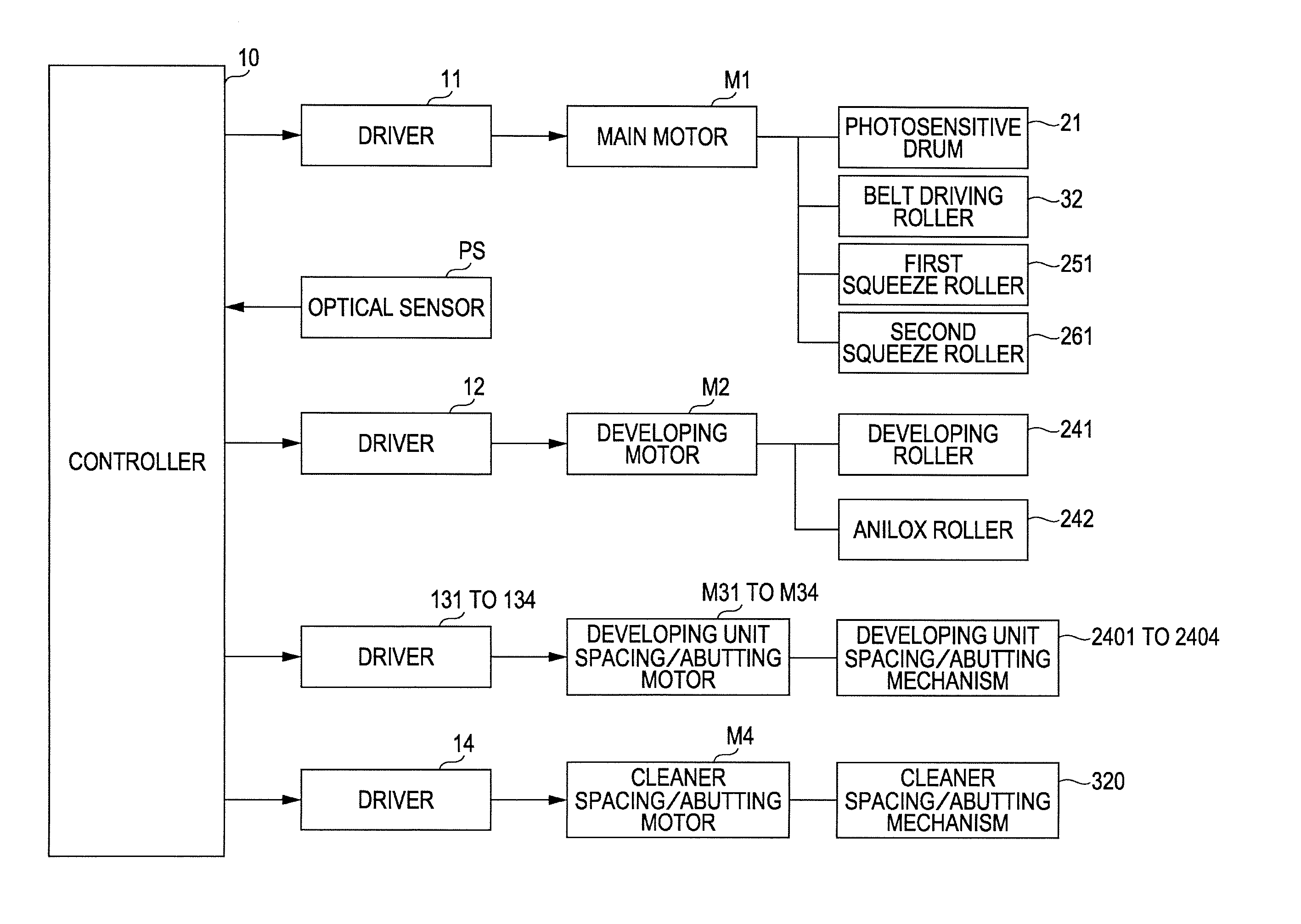
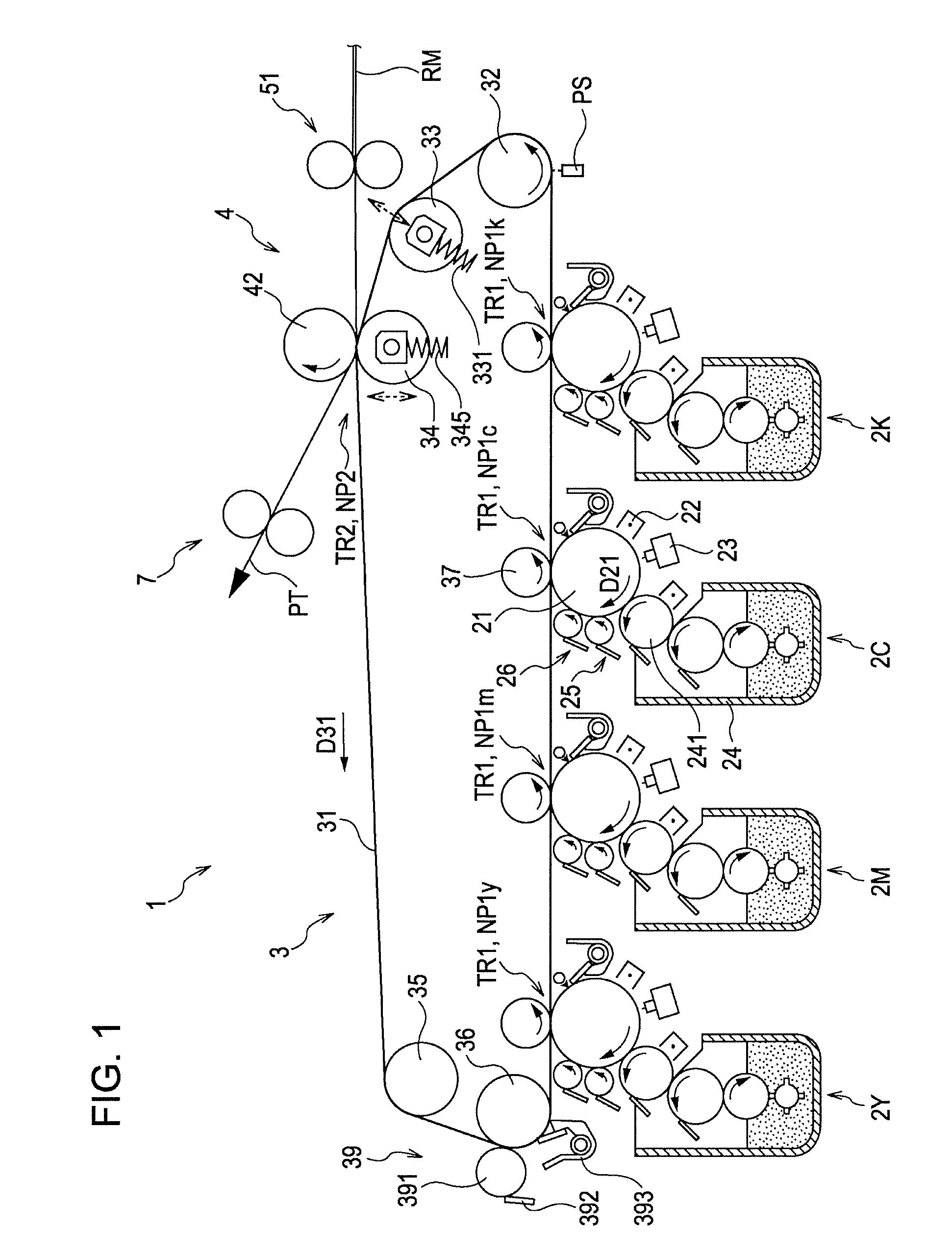
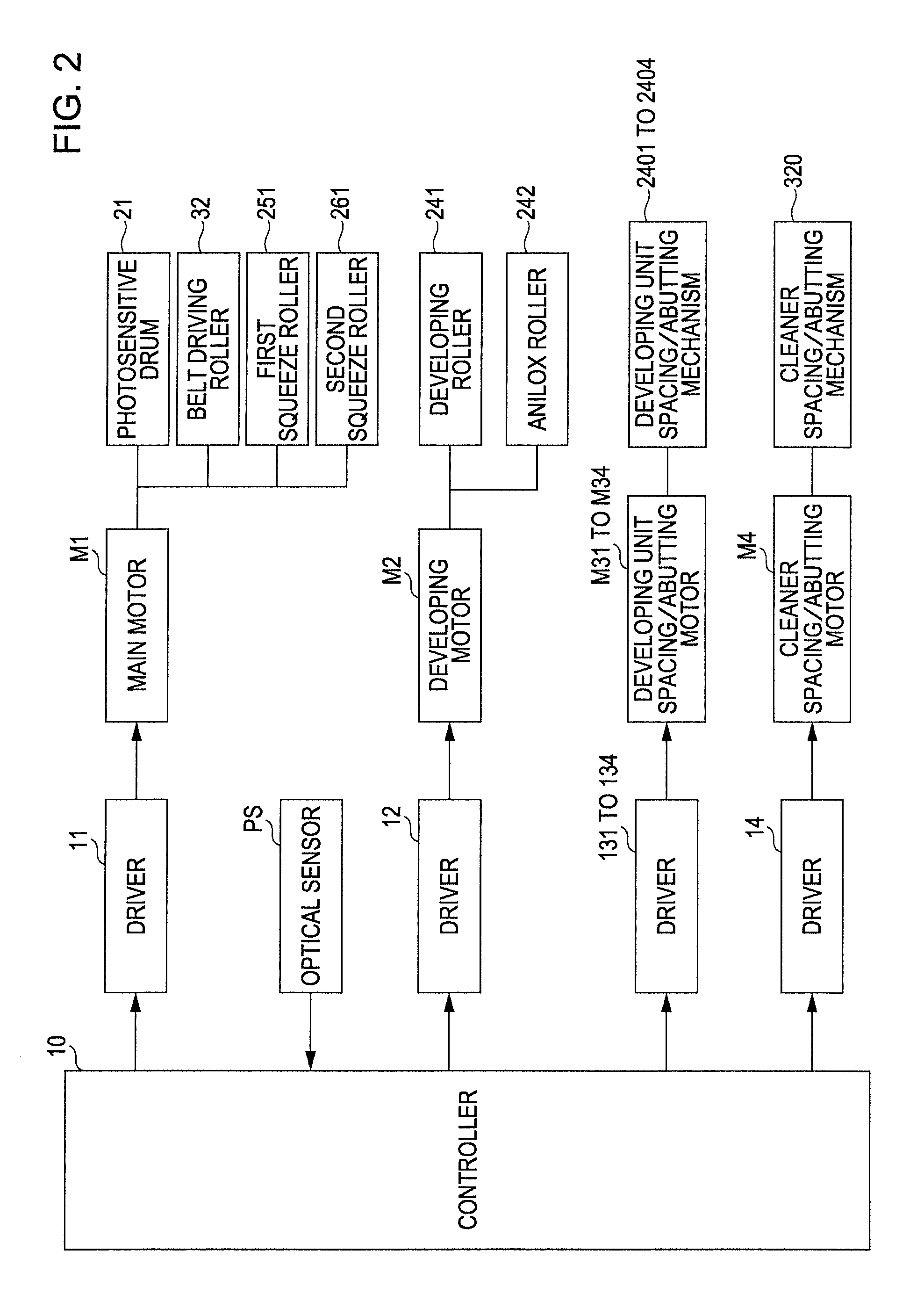
[0032]FIG. 1 is a view illustrating an image forming apparatus according to the invention. FIG. 2 is a block diagram illustrating an electric configuration of the apparatus in FIG. 1. An image forming apparatus 1 includes four image forming stations 2Y (for yellow), 2M (for magenta), 2C (for cyan), and 2K (for black) for forming images of different colors. The image forming apparatus 1 can selectively execute a color mode in which toner of four colors, yellow (Y), magenta (M), cyan (C) and black (K), are superposed to form a color image, and a monochromatic mode in which only black (K) toner is used to form an monochromatic image. In this image forming apparatus, when an image forming instruction signal is fed to a controller 10 having a CPU or a memory from an external apparatus such as a host computer, the controller 10 controls respective sections of the apparatus to execute a desired operation of image formation and thereby forms images corresponding to the image forming instruc...

second embodiment

[0095]In addition, in the second embodiment, the secondary transfer nip portion NP2 corresponds to the “fifth transfer nip portion” of the invention.

[0096]In this case, the invention is not limited to the above-mentioned embodiments, and various modifications may be made within the purpose of the invention. For example, although the image forming stations 2Y, 2M, 2C and 2K are arranged in series in the above-mentioned embodiment, the arranging relationship is not limited thereto. In addition, four image forming stations are arranged in series along the winding direction of the belt-type intermediate transfer member 31, but the number or arrangement of the image forming stations is not limited thereto.

[0097]In addition, although the belt-type intermediate transfer member 31 is used as the “transfer medium” of the invention in the above-mentioned embodiments, for example, a drum-type intermediate transfer member may be used.


PUM


Abstract

The image forming apparatus includes a first latent image carrier; a first developing member develops the latent image by a first liquid developer; a second latent image carrier; a second developing member develops the latent image by a second liquid developer; a transfer medium that forms first and second nip portion; a detecting unit; and a control unit, that, when the first image is a first image density, detect the first image passed through the second nip portion formed by the transfer medium and the second latent image carrier while the second developing member contacts with the second latent image carrier, and when the first image is a second image density higher than the first image density, detect the first image passed through the second nip portion formed by the transfer medium and the second latent image carrier while the second developing member separates form the second latent image carrier.

Description

BACKGROUND[0001]1. Technical Field[0002]The present invention relates to an image forming apparatus and an image forming method which can form an image by developing a latent image with a liquid developer containing a liquid carrier and toner, and detect the corresponding image.[0003]2. Related Art[0004]In the related art, an image forming apparatus of an electrophotographic type has been put to practical use, in which a latent image carrier, such as a photosensitive drum charged with electricity, is exposed to by an exposure unit to form an electrostatic latent image on the latent image carrier, the electrostatic latent image is developed by adhering toner to the latent image carrier with a developing unit to form a toner image, and then the toner image is transferred onto a transfer paper to obtain a desired image. As a developing method of the developing unit, a liquid developing method using a developing liquid with toner dispersed in a liquid carrier is known. The liquid develo...

Claims


Application Information

Patent Timeline
Patent Type & Authority Applications(United States)
IPC IPC(8): G03G15/00
CPCG03G15/0121G03G15/10G03G2215/00059G03G15/5058G03G2215/0626G03G15/0131G03G15/161G03G2215/0193
Inventor TOYAMA, HIROSHIIKUMA, KEN
Owner SEIKO EPSON CORP
Learn More