
Terminal unit for secondary battery and method of manufacturing the same

a secondary battery and terminal unit technology, applied in the direction of cell components, final product manufacturing, sustainable manufacturing/processing, etc., can solve the problem of poor weldability

Active Publication Date: 2011-05-05
ROBERT BOSCH GMBH +1
View PDF13 Cites 21 Cited by
  • Summary
  • Abstract
  • Description
  • Claims
  • Application Information

AI Technical Summary

Benefits of technology

[0007]It is a feature of an embodiment to provide a terminal unit for a secondary battery that ensures strong coupling even when welding between heterogeneous metals, and a method of manufacturing the same.

Problems solved by technology

Thus, if the rivet terminal is formed of a different material from the materials of the positive electrode rivet and / or negative electrode rivet, heterogeneous metal welding may be performed between the electrode rivet and the rivet terminal, resulting in poor weldability.

Method used


Image

  • Terminal unit for secondary battery and method of manufacturing the same
  • Terminal unit for secondary battery and method of manufacturing the same
  • Terminal unit for secondary battery and method of manufacturing the same

Examples


Embodiment Construction

[0021]Korean Patent Application No. 10-2009-0104306, filed on Oct. 30, 2009, in the Korean Intellectual Property Office, and entitled: “Terminal Unit for Secondary Battery and Method of Manufacturing the Same,” is incorporated by reference herein in its entirety.

[0022]Example embodiments will now be described more fully hereinafter with reference to the accompanying drawings; however, they may be embodied in different forms and should not be construed as limited to the embodiments set forth herein. Rather, these embodiments are provided so that this disclosure will be thorough and complete, and will fully convey the scope of the invention to those skilled in the art.

[0023]In the drawing figures, the dimensions of layers and regions may be exaggerated for clarity of illustration. It will also be understood that when a layer or element is referred to as being “on” another element, it can be directly on the other element, or intervening elements may also be present. In addition, it wil...


PUM

PropertyMeasurementUnit
currentaaaaaaaaaa
weldabilityaaaaaaaaaa
dimensionsaaaaaaaaaa

Abstract

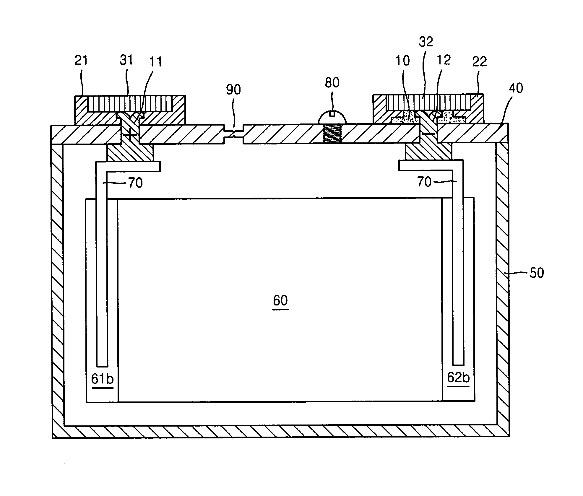
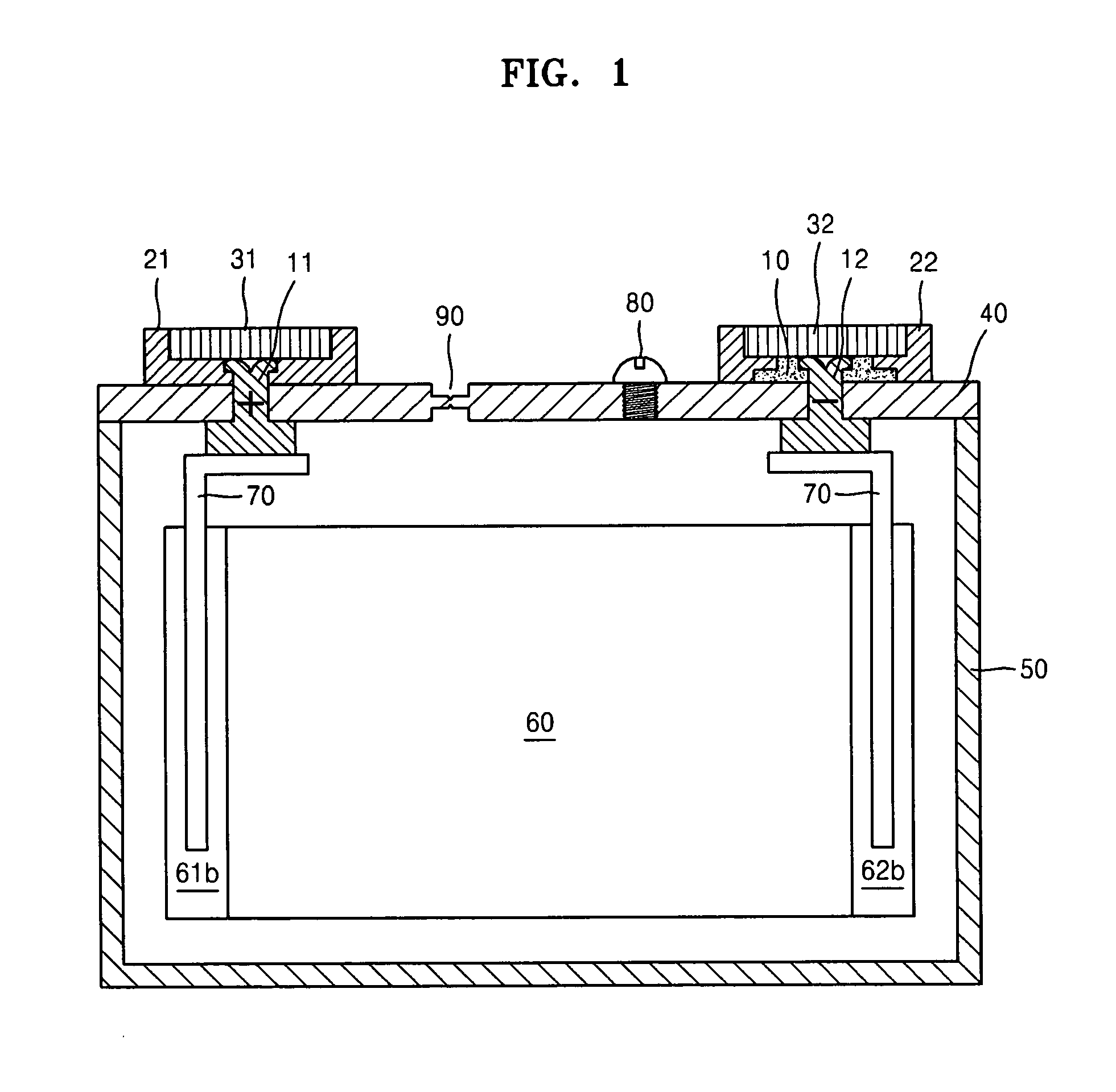
A terminal unit of a secondary battery and a method of manufacturing the same, the terminal unit including an electrode rivet, the electrode rivet being connected to an electrode assembly; a rivet terminal, the rivet terminal including a metal different from a metal of the electrode rivet; and a medium plate, the medium plate including a same metal as the electrode rivet, and being disposed between the electrode rivet and the rivet terminal so as to be overlap-weldable to the rivet terminal.

Description

BACKGROUND[0001]1. Field[0002]Embodiments relate to a terminal unit for a secondary battery and a method of manufacturing the same.[0003]2. Description of the Related Art[0004]Secondary batteries are rechargeable batteries widely used in portable electronic devices, e.g., mobile phones, notebook computers, and camcorders. A secondary battery may include a case having an open portion, an electrode assembly accommodated in the case and including a positive electrode, a negative electrode, and a separator wound in a jelly-roll shape, and a cap assembly covering the open portion of the case. In addition, a current collecting plate may be disposed on an end of the electrode assembly. The current collecting plate may be electrically connected to a terminal arranged in the cap assembly. Thus, when the terminal of the cap assembly is connected to an external terminal, a current generated in the electrode assembly may be supplied to the external terminal via the current collecting plate and ...

Claims


Application Information

Patent Timeline
Patent Type & Authority Applications(United States)
IPC IPC(8): H01M4/02B23K20/12B23K26/20H01M4/04H01M50/562H01M50/566
CPCB23K20/122H01M2/30B23K2201/38B23K26/20B23K26/244B23K2101/38Y02E60/10Y02P70/50H01M50/562H01M50/566
Inventor BYUN, SANG-WONKIM, SUNG-BAE
Owner ROBERT BOSCH GMBH
Learn More