
Transducer Unit Incorporating an Acoustic Coupler

a transducer and acoustic coupler technology, applied in the field of acoustic couplers for transducers, can solve the problems of image distortion and image quality degradation, uncontrollable and variable thickness and shape of fluid gap between transducer and breast support plate, and restricting the choice of fluids available for us

Inactive Publication Date: 2011-05-05
KONINKLIJKE PHILIPS ELECTRONICS NV
View PDF1 Cites 13 Cited by
  • Summary
  • Abstract
  • Description
  • Claims
  • Application Information

AI Technical Summary

Benefits of technology

[0004]It is an object of the present invention to provide an acoustic coupler for a transducer unit of an ultrasonic imaging system which overcomes the problems outlined above, and allows for the use of coupling fluids with desirable chemical and mechanical properties, irrespective of their speed of sound, acoustic impedance, attenuation, or other acoustic properties.
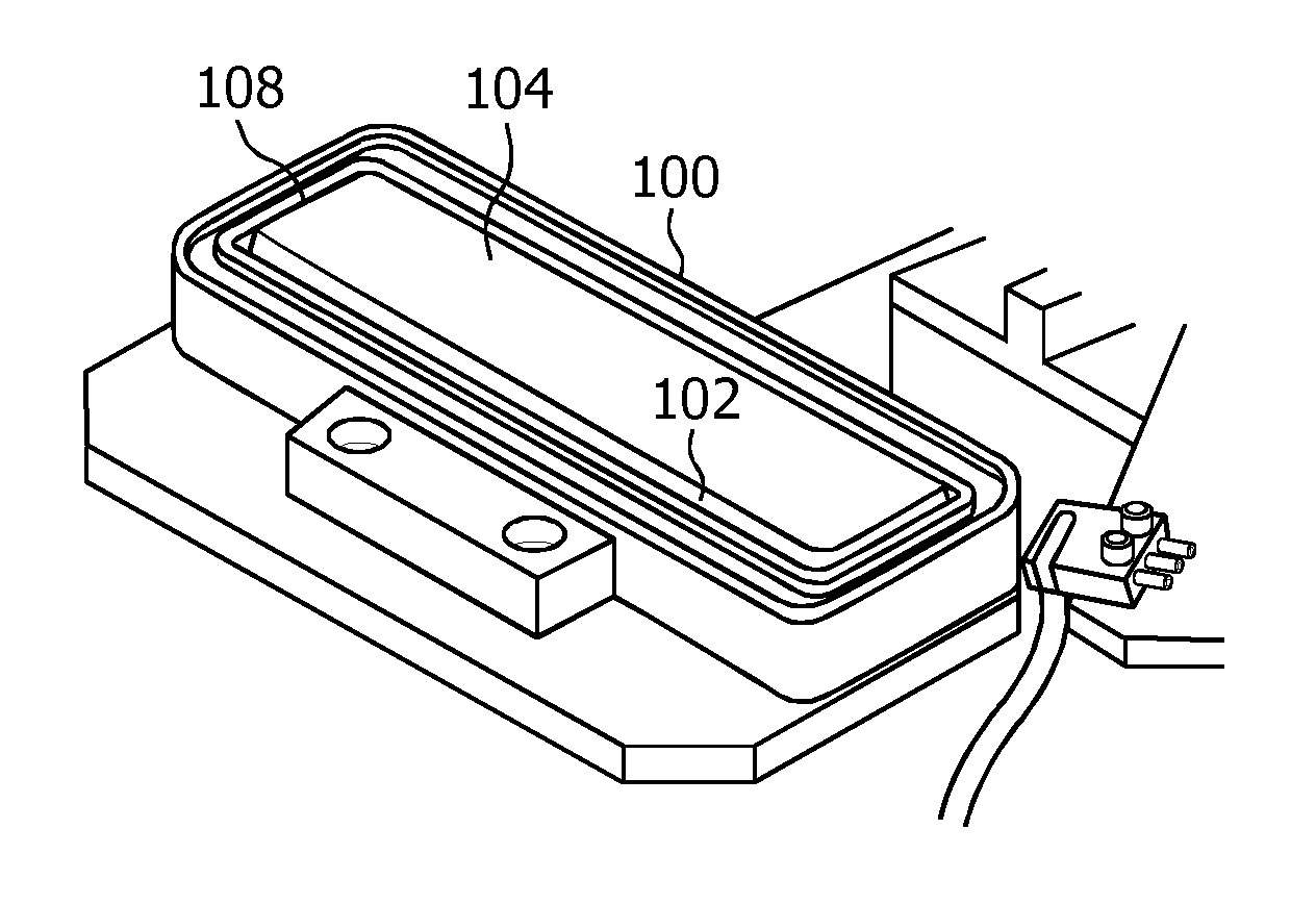
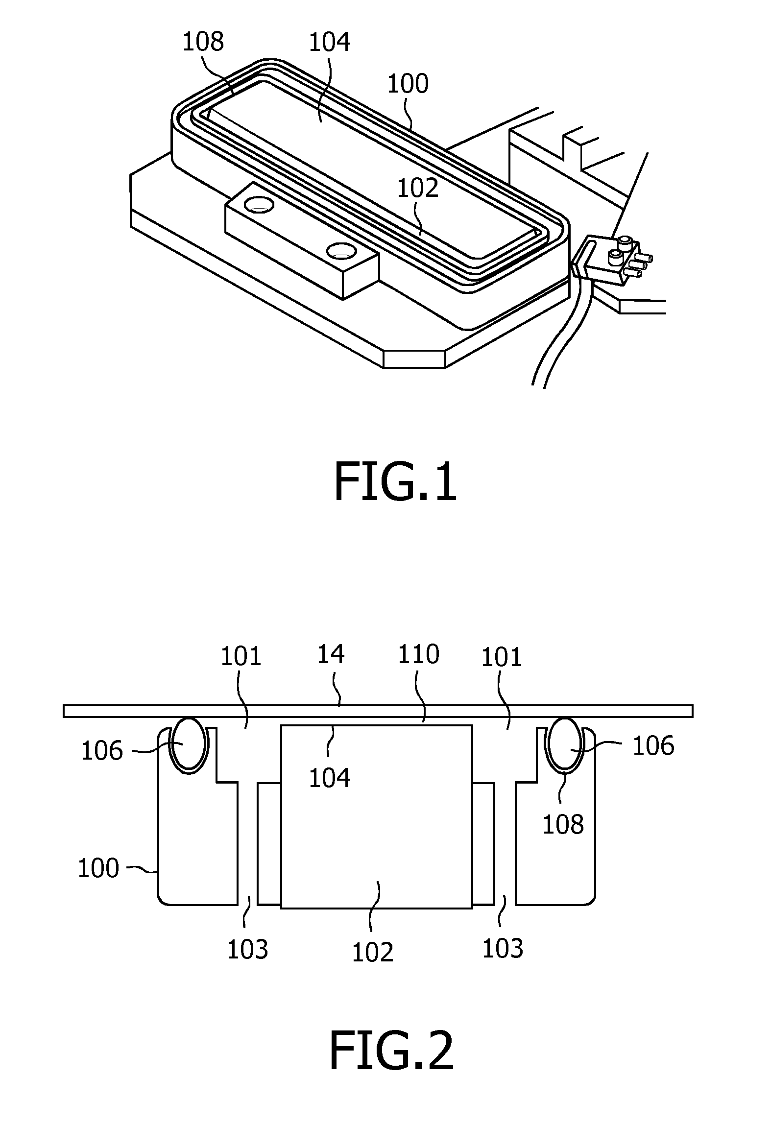
[0014]Thus, the ultrasonic breast imaging system and the transducer unit of the present invention employ an acoustic coupler which provides a compact, lightweight, leak proof and reliable way to couple the transducer, in an ultrasonic imaging system, to the compression plate, in any orientation.

Problems solved by technology

In these implementations, both the thickness and shape of the fluid gap between the transducer and the breast support plate is uncontrolled and variable over the scanning area.
If the speed of sound of the coupling fluid does not closely match the average speed of body tissue, then significant refraction and defocusing of the ultrasound beam can result, causing image distortion and degradation of image quality.
This severely restricts the choices of fluids available for use, and complicates the design of such systems.
Furthermore, the above-mentioned coupling methods are heavy, messy and subject to leakage, which factors restrict the use of such systems in a clinical environment.

Method used


Image

  • Transducer Unit Incorporating an Acoustic Coupler
  • Transducer Unit Incorporating an Acoustic Coupler
  • Transducer Unit Incorporating an Acoustic Coupler

Examples


Embodiment Construction

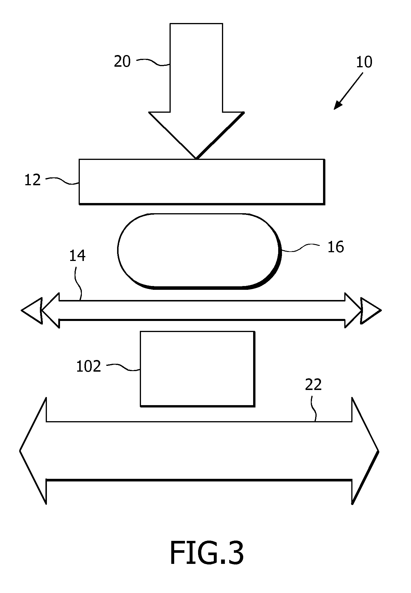
[0024]Thus, as mentioned above, ultrasonic imaging has been used for many years to produce diagnostic images of the breast. Ultrasound systems are now being developed that, unlike earlier systems, produce a volumetric (3D) image of the breast. This may be done by scanning the breast with a moving array transducer. An array transducer can transmit and receive electronically steered beams, which can scan a plane of a subject without moving the transducer. As the array transducer is moved in the elevation direction, it successively scans a sequence of planes. The planes can be considered to be analogous to a pack of playing cards which are aligned in a pile. The plane of each playing card is a planar image, and a stack of the cards comprises a stack of planar images of a volumetric object which are aligned in parallel. The data of such a sequence of planes can be sued to render three-dimensional (3D) images, as is known in the art.

[0025]In order to scan the, breast accurately with a mo...


PUM


Abstract

The present invention relates to a transducer unit for an ultrasonic breast imaging system, in which an acoustic coupler is employed which comprises a frame in which a transducer is mounted. The frame is open at one end, and a surface of the transducer is exposed at the open end. The frame and exposed transducer surface are put under compression against the surface of a compression plate with a gasket, or similar, providing a fluid-tight seal therebetween. A thin layer of acoustic couplant is provided between the transducer surface and the compression plate. The frame defines a chamber around the nonexposed surface of the transducer, the chamber housing an acoustic couplant.

Description

FIELD OF THE INVENTION[0001]This invention relates to an acoustic coupler for a transducer unit for use in an ultrasonic imaging system and, more particularly, to a transducer unit which is especially suited for use in an ultrasonic breast system arranged and configured to acquire ultrasound scans of a compressed breast for use in breast evaluation and / or adjunctive ultrasound mammography, or other applications requiring reliable and repeatable three-dimensional breast ultrasound data.BACKGROUND OF THE INVENTION[0002]Ultrasonic imaging has rapidly become the preferred modality for the non-invasive investigation of human tissues. In particular, ultrasonic imaging has been used for many years to produce diagnostic images of the breast. For example, U.S. Pat. No. 4,298,009 describes a breast scanning arrangement consisting of a patient table on which a patient lies in the face-down position. The patient table is provided with a hole through which the patient suspends a breast into a ta...

Claims


Application Information

Patent Timeline
IPC IPC(8): A61B8/14A61B8/00A61B8/08
CPCA61B8/0825A61B8/4455A61B8/4281A61B8/4209
Inventor ENTREKIN, ROBERT RANDALL
Owner KONINKLIJKE PHILIPS ELECTRONICS NV
Learn More