Fuel delivery system control strategy

a technology of fuel delivery system and control strategy, which is applied in the direction of electric control, positive displacement liquid engine, instruments, etc., can solve the problems of reducing the output of the lower pressure pump, reducing the energy consumed by the lower pressure fuel pump, and reducing the combustion efficiency of the engine. , to achieve the effect of reducing emissions, increasing combustion efficiency, and reducing emissions

Active Publication Date: 2011-05-05
FORD GLOBAL TECH LLC
View PDF15 Cites 33 Cited by
  • Summary
  • Abstract
  • Description
  • Claims
  • Application Information

AI Technical Summary

Benefits of technology

[0001]Engines may use Gasoline Direct Fuel Injection (GDI) systems to deliver fuel over a wide range of operating conditions to increase the combustion efficiency and decrease emissions. However, under certain operating conditions, vapor formation may occur in the fuel delivery system, which in turn may degrade engine combustion efficiency.

Problems solved by technology

However, under certain operating conditions, vapor formation may occur in the fuel delivery system, which in turn may degrade engine combustion efficiency.
However, the inventors herein have recognized several issues with the above approach.
However, because of the positioning of the pressure regulator in the '051 reference, the pressure regulator's response curve provides no indication of such upstream vapor formation.
Therefore, the output of the lower pressure pump may be decreased, thereby decreasing the energy consumed by the lower pressure fuel pump while decreasing the likelihood of fuel vapor development within the fuel delivery system.
In particular, the method may decrease the wear on the higher pressure pump due to vaporization of fuel within and / or upstream the higher pressure pump (e.g. step-room).

Method used


Image

  • Fuel delivery system control strategy
  • Fuel delivery system control strategy
  • Fuel delivery system control strategy

Examples


Embodiment Construction

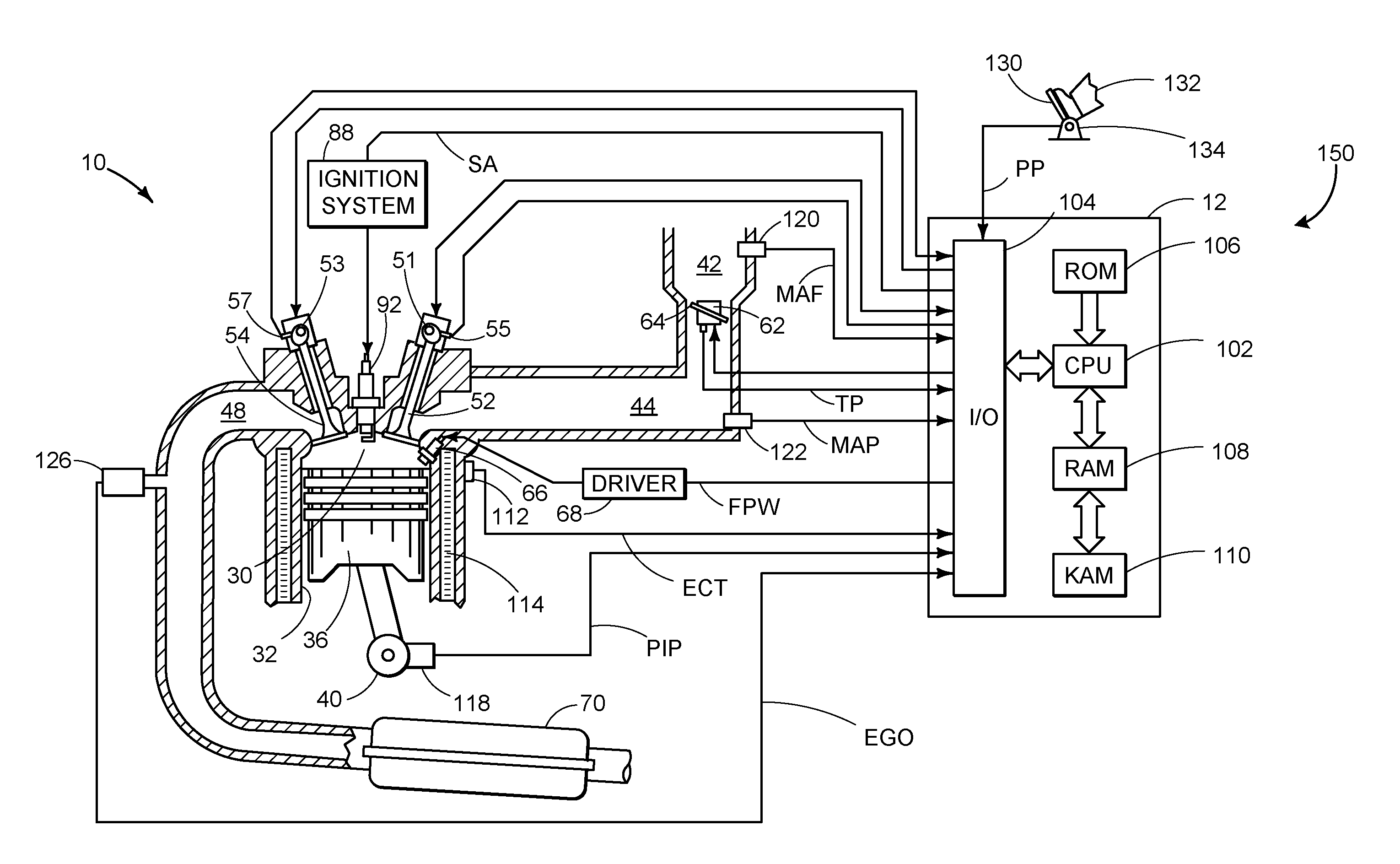
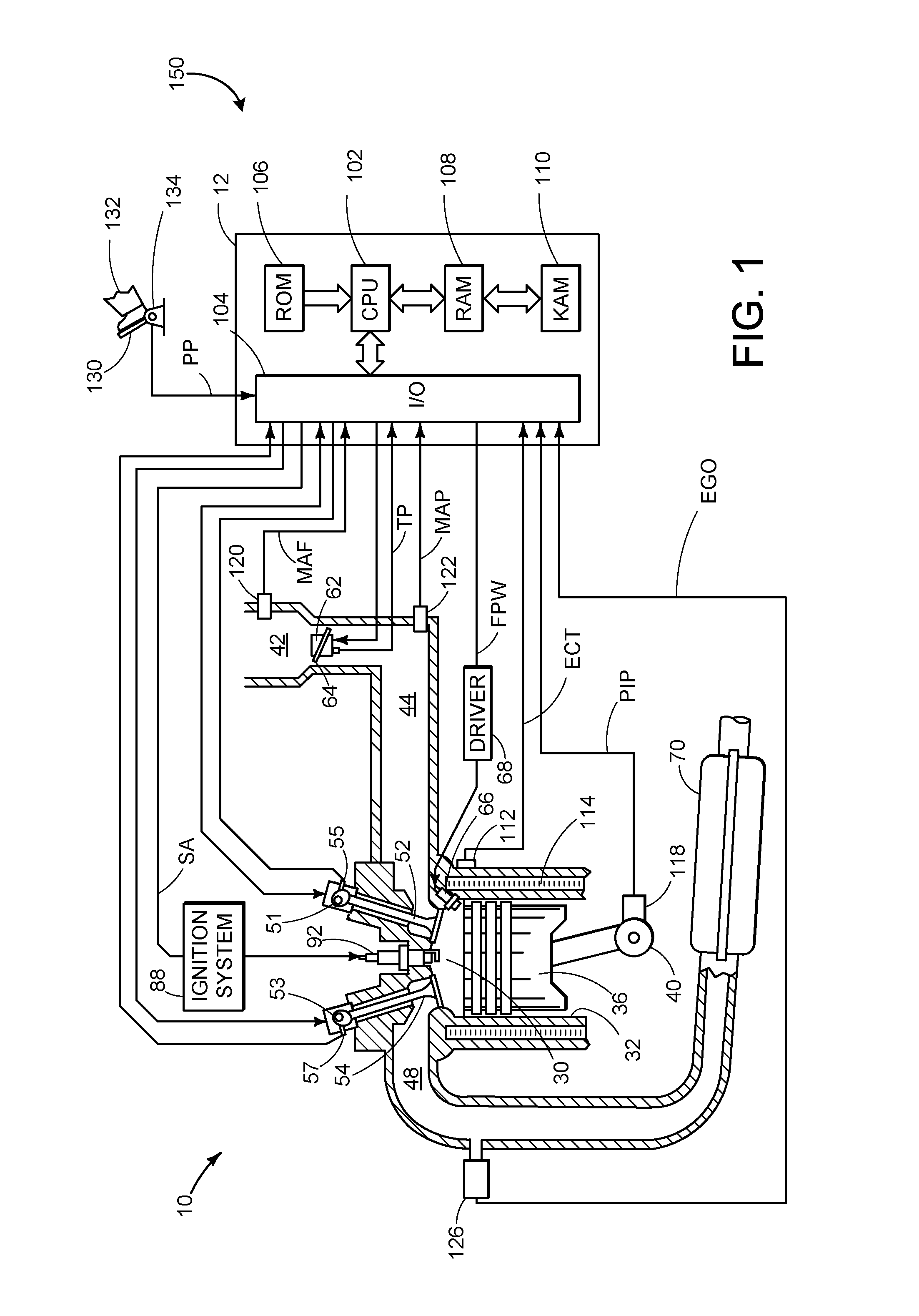
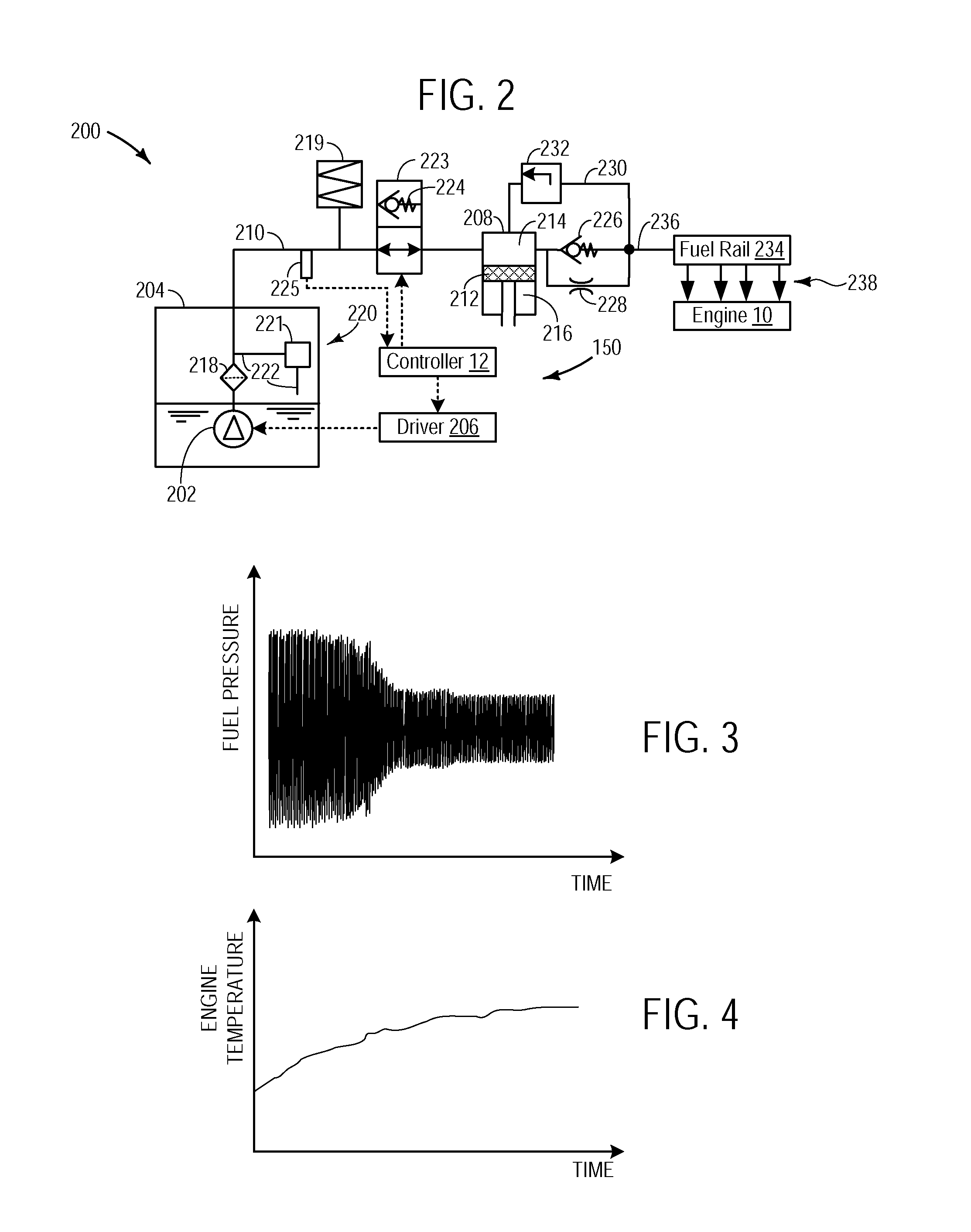
[0014]The present description discloses systems and methods for an engine system such as shown in FIG. 1, including an upstream a lower pressure pump and a downstream higher pressure fuel pump system as illustrated in FIG. 2. The systems and methods include adjusting an output of the lower pressure pump and higher pressure pump based on pressure fluctuations at an inlet of a higher pressure pump. In particular, as illustrated in FIGS. 3-4, pressure oscillations, at or above a given frequency, of the fuel pressure at the inlet of the higher pressure pump may be indicative of vapor formation. Thus, by monitoring the pressure oscillations, it may be possible to identify vapor generation, or the potential for vapor generation, and modify the pump operation in response thereto. For example, as illustrated in the routines of FIGS. 5-6, in response to pressure oscillations at the high pressure pump inlet, the lower pressure pump may be adjusted to reduce vapor formation. Further, various a...


PUM


Abstract

A method for a fuel delivery system coupled to an engine is disclosed, the fuel delivery system including a lower pressure pump (LPP) fluidly coupled upstream of a higher pressure pump (HPP). The method may include during operation of both the HPP and LPP, adjusting operation of the LPP in response to pressure fluctuations at an inlet of the HPP.

Description

BACKGROUND AND SUMMARY[0001]Engines may use Gasoline Direct Fuel Injection (GDI) systems to deliver fuel over a wide range of operating conditions to increase the combustion efficiency and decrease emissions. However, under certain operating conditions, vapor formation may occur in the fuel delivery system, which in turn may degrade engine combustion efficiency.[0002]Various approaches have been used to decrease vapor formation. For example, in U.S. Pat. No. 7,438,051, a control strategy for decreasing the vapor in a fuel delivery system downstream of a high pressure pump is disclosed. In particular, the control strategy involves monitoring the response curve of a pressure regulator in the fuel delivery system to detect formation of vapor bubbles downstream of a high pressure pump, and subsequently adjusting the fuel delivery system to reduce the vapor in the fuel delivery system downstream of the high pressure pump.[0003]However, the inventors herein have recognized several issues ...

Claims


Application Information

Patent Timeline
Patent Type & Authority Applications(United States)
IPC IPC(8): F02D41/00F02M37/04
CPCF02D33/003F02D41/3854F02M37/0058F02D2250/02F02D2200/0602
Inventor PURSIFULL, ROSS D.
Owner FORD GLOBAL TECH LLC
Why Eureka
Try Eureka