Needle attaching structure of rotating shaft and meter device

Active Publication Date: 2011-05-12
YAZAKI CORP
View PDF5 Cites 11 Cited by
  • Summary
  • Abstract
  • Description
  • Claims
  • Application Information

AI Technical Summary

Benefits of technology

[0013]The present invention is devised by considering the above-described circumstances and it is an object of the present invention to provide a needle attaching structure of a rotating shaft and a meter device in which a light emitting efficiency of a needle is not extremely deteriorated, an illuminating light can be efficiently transmitted to the needle and the generation of cracks can be prevented.
[0017]According to the needle attaching structure described in the above-described (1) or (2), a space between the press-in part and the press-in hole can be more reduced than, for instance, a case of a triangular form in section. Accordingly, the light emitting efficiency of the needle is not seriously deteriorated by the leakage of the light from the space, so that the illuminating light can be efficiently transmitted to the needle. Further, since the press-in part has a structure that a rather large number of angular parts of a polygonal form (however, excluding too many angular parts) are respectively distributed to come into contact with the press-in hole, differently from the press-in part of the true circular form in section which comes into contact with the press-in hole in an entire peripheral surface or the press-in part of a triangular form in section which concentrically comes into contact with the press-in hole at a small number of parts such as three angular parts, a large press-in load can be avoided from being concentrically applied to the press-in hole. As a result, even in the needle made of a synthetic resin and having a relatively low strength, the cracks can be prevented from being generated in the press-in hole.
[0026]According to the meter device described in the above-described (3) or (4), the light emitting efficiency of the needle is not seriously deteriorated because of the same reason, so that the illuminating light can be efficiently transmitted to the needle and the generation of the cracks can be prevented. Further, the length of the intersecting line is adjusted (changed), so that the press-in load can be set to a proper level so as not to generate the cracks in the needle sheath part and the needle can be assuredly attached to the rotating shaft.
[0027]According to the needle attaching structure of the rotating shaft and the meter device of the present invention, the space between the press-in part and the press-in hole can be more reduced than, for instance, a case of a triangular form in section. Accordingly, the light emitting efficiency of the needle is not seriously deteriorated by the leakage of the light from the space, so that the illuminating light can be efficiently transmitted to the needle. Further, since the press-in part has a structure that only a rather large number of angular parts of a polygonal form respectively come into contact with the press-in hole, differently from the press-in part of the true circular form in section which comes into contact with the press-in hole in an entire peripheral surface or the press-in part of a triangular form in section which concentrically comes into contact with the press-in hole at a small number of parts such as three angular parts, a large press-in load can be avoided from being concentrically applied to the press-in hole. Thus, even in the needle made of a synthetic resin and having a relatively low strength, the cracks can be advantageously prevented from being generated in the press-in hole.
[0028]Further, the press-in load of the rotating shaft to the press-in hole is proportional to the contact area thereof, and the contact area is changed depending on the length of the intersecting line in which each vertex of the rotating shaft comes into contact with the inner peripheral surface of the press-in hole. Accordingly, when the length of the intersecting line is adjusted (changed), the press-in load can be preferably set to a proper level so as not to generate the cracks in the needle sheath part and the needle can be advantageously assuredly attached to the rotating shaft.

Problems solved by technology

Accordingly, when there is a large unevenness in working accuracy between these parts, when the needle is pressed-in to the needle shaft, since the needle is loosely attached to the needle shaft, the needle is easily slipped out from the needle shaft.
As a result, a large quantity of light leaks from the space, so that a rate of illuminating light guided to reach the needle is greatly reduced to deteriorate a light emitting efficiency.
Especially, when a section of the fitting part has a triangular form, the space is so large as not to be neglected, so that a rate of the leakage of the light is increased.
Further, in such a needle attaching structure, when the fitting part having a section of, for instance, a triangular form is pressed-in to the attaching hole H of the needle, since a difference between levels of press-in loads of contact parts in corner parts respectively is larger than that of non-contact parts of the corner parts which do not respectively come into contact with the attaching hole H, there is a fear that cracks are generated due to a stress concentration in the corner parts respectively.
The above-described needle attaching structure has a problem in view of the above-described point.

Method used


Image

  • Needle attaching structure of rotating shaft and meter device
  • Needle attaching structure of rotating shaft and meter device
  • Needle attaching structure of rotating shaft and meter device

Examples


Embodiment Construction

[0042]Now, an exemplary embodiment of the present invention will be described below in detail by referring to the attached drawings.

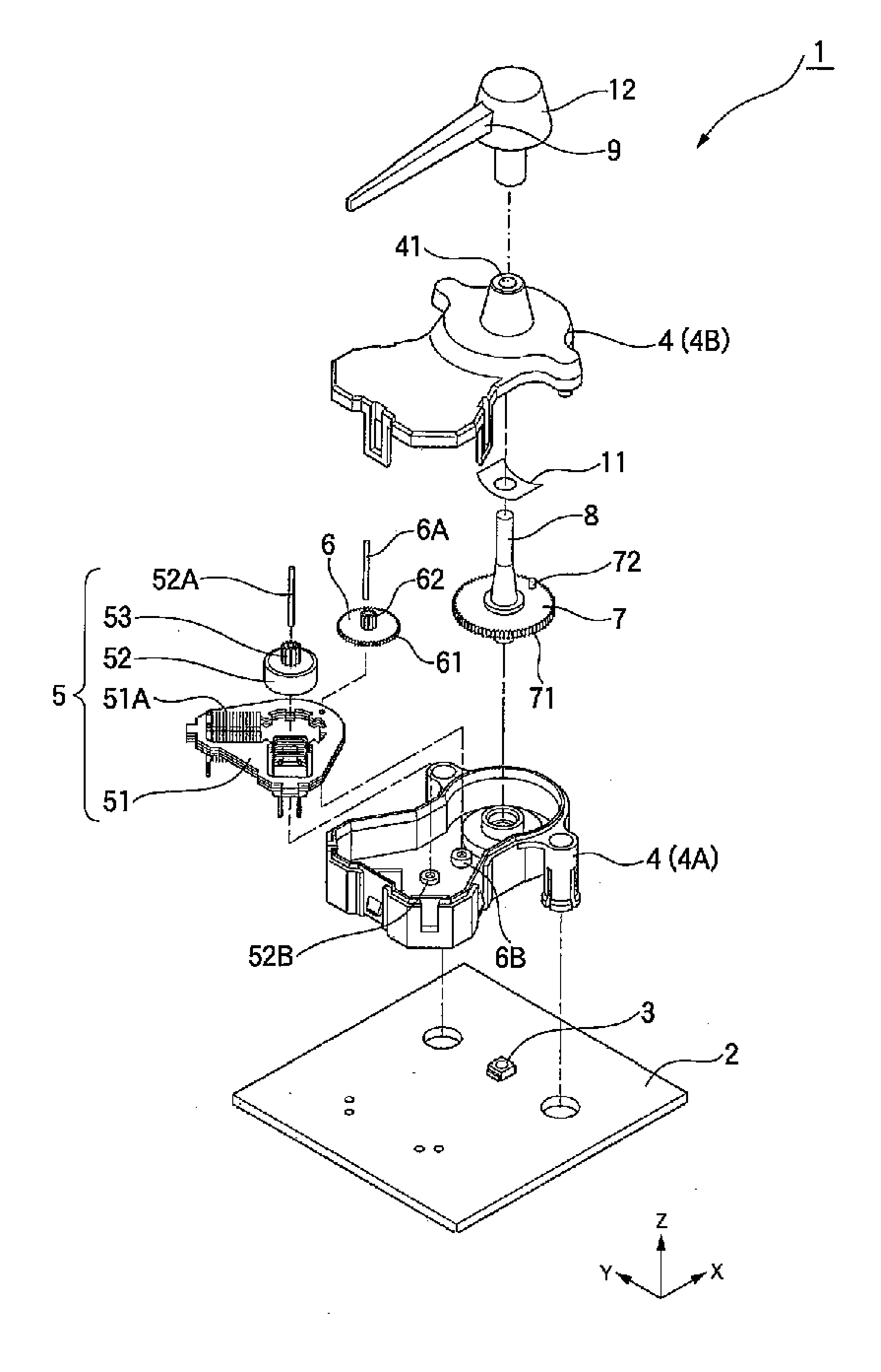
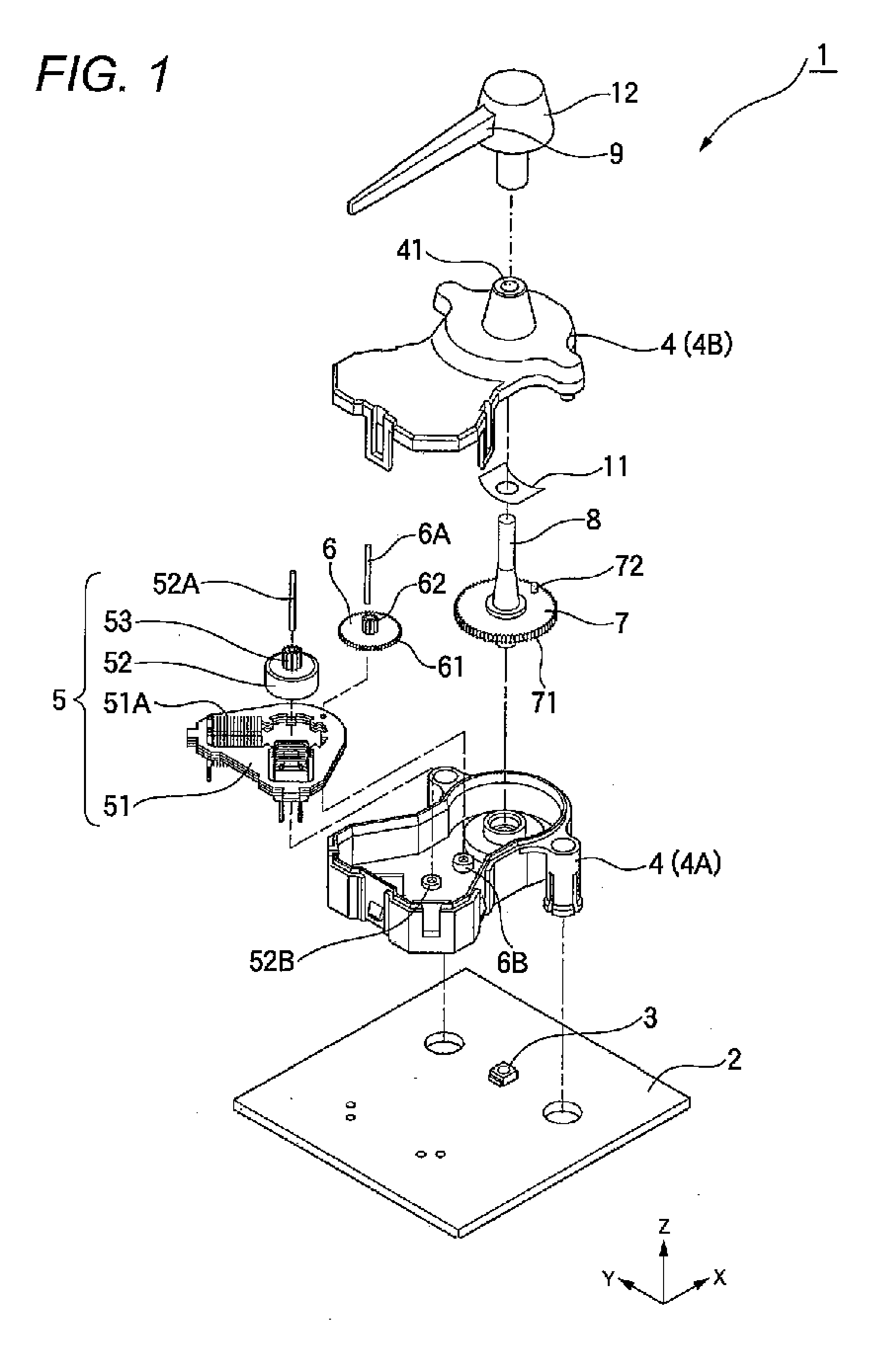
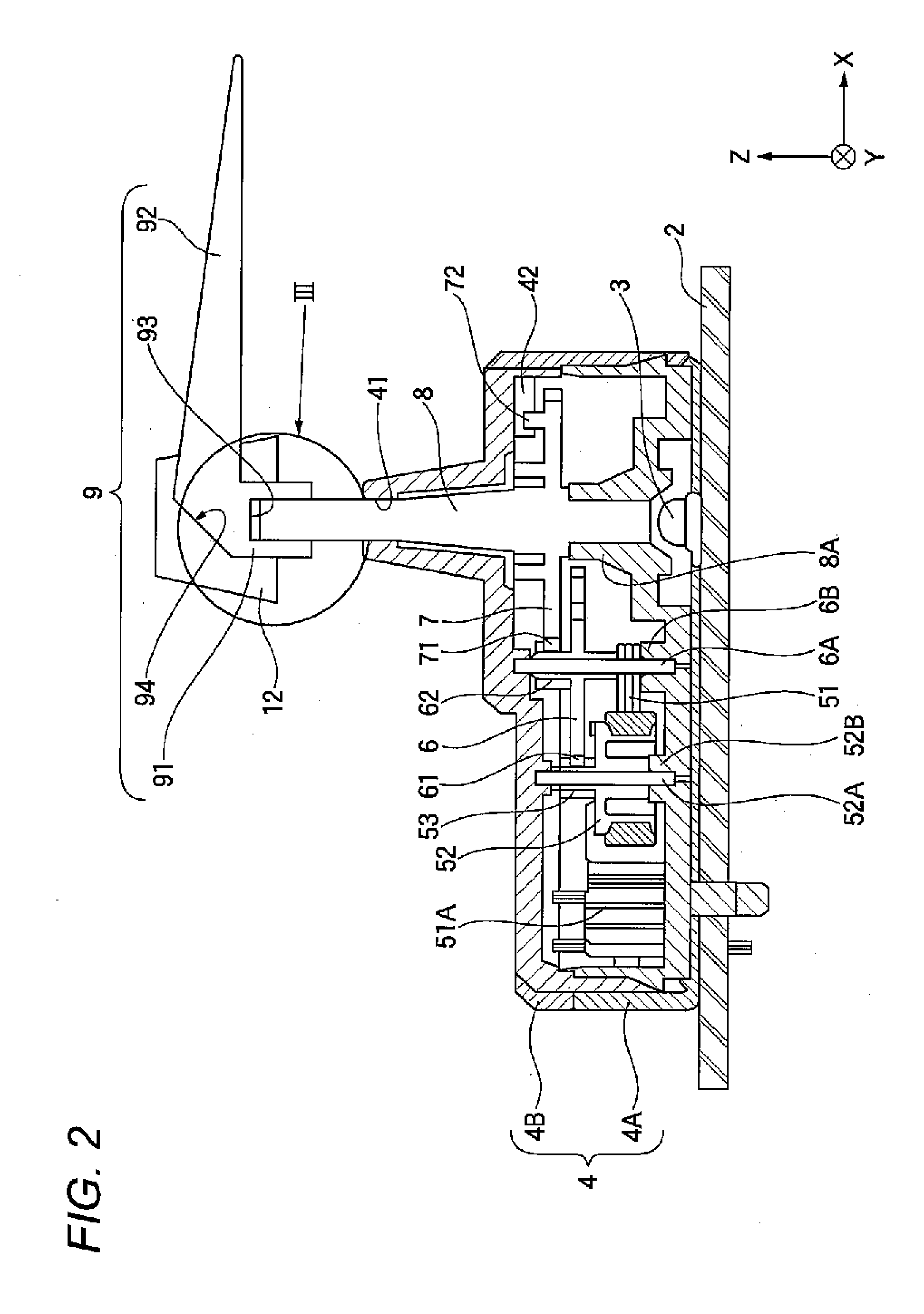
[0043]FIGS. 1 and 2 show a meter device 1 having a rotating shaft to which a needle attaching structure of the present invention is applied.

[0044]The meter device 1 includes a light source 3 mounted on a substrate 2, a meter case 4 attached to a prescribed position on the substrate 2 including an area where the light source 3 is mounted and a display plate not shown in the drawing that is arranged on the meter case 4 and displays necessary information about a vehicle itself or an environment in the periphery of the vehicle such as numeric characters, characters, signs or the like.

[0045]The meter device 1 of the present exemplary embodiment forms a part of a combination meter not shown in the drawing. The display plate forming a front surface side is fitted to an entire surface to form a reverse plate. Further, in the display plate, various kinds of disp...


PUM

PropertyMeasurementUnit
Lengthaaaaaaaaaa
Diameteraaaaaaaaaa

Abstract

When a press-in part 81 is pressed-in to a press-in hole 93, a vertex of the press-in part 81 deformed to a form along the inner surface of the press-in hole 93 comes into contact with the inner surface of the press-in hole 93 and a press-in force when the press-in part 81 is inserted into the press-in hole 93 or a pull-out force when the press-in part 81 is pulled out from the press-in hole 93 is set in according with the length of an intersecting line that a surface on which the outer surface of the press-in part 81 comes into contact with the inner surface of the press-in hole 93 and a section intersecting orthogonally to the axial direction of the press-in part 81 intersect.

Description

BACKGROUND[0001]1. Field of the Invention[0002]The present invention relates to a rotating shaft to which a needle is attached that indicates numeric characters of a dial in a meter device of a meter of a vehicle or the like, and more particularly to a needle attaching structure of a rotating shaft in which when the needle is pressed-in to the rotating shaft, a stress is not concentrated to a part, so that the needle can be integrally attached.[0003]2. Description of the Related Art[0004]In such a kind of meter device to be mounted on the vehicle or the like, ordinarily, the dial in which characters, numeric characters and a scale are provided is lighted from a back surface side by an exclusive light source or the needle for indicating the characters or the numeric characters of the dial is lighted (for instance, see patent literature 1).[0005]Specifically, as such a meter device, as shown in FIG. 9, for instance, a meter device is known that includes in a meter box 102 under a dial...

Claims


Application Information

Patent Timeline
IPC IPC(8): B23P11/00
CPCB60K35/00B60K2350/203Y10T29/53996G01D13/265B60K37/02G01D11/28B60K35/60B60K2360/33B60K2360/6992
Inventor AONO, YUUSUKETOTSUKA, SHIGEKI
Owner YAZAKI CORP
Why Eureka
Try Eureka