Metal joint and building comprising the same
a technology of metal joints and building components, applied in the field of metal joints, can solve the problems of reducing the bending yield of the bending panel or the shear and improving the degree of freedom, reducing the horizontal strength of the entire building, and reducing the bending yield of the bending panel
- Summary
- Abstract
- Description
- Claims
- Application Information
AI Technical Summary
Benefits of technology
Problems solved by technology
Method used
Image
Examples
first embodiment
[0109]A first embodiment of the present invention will be described below with reference to drawings.
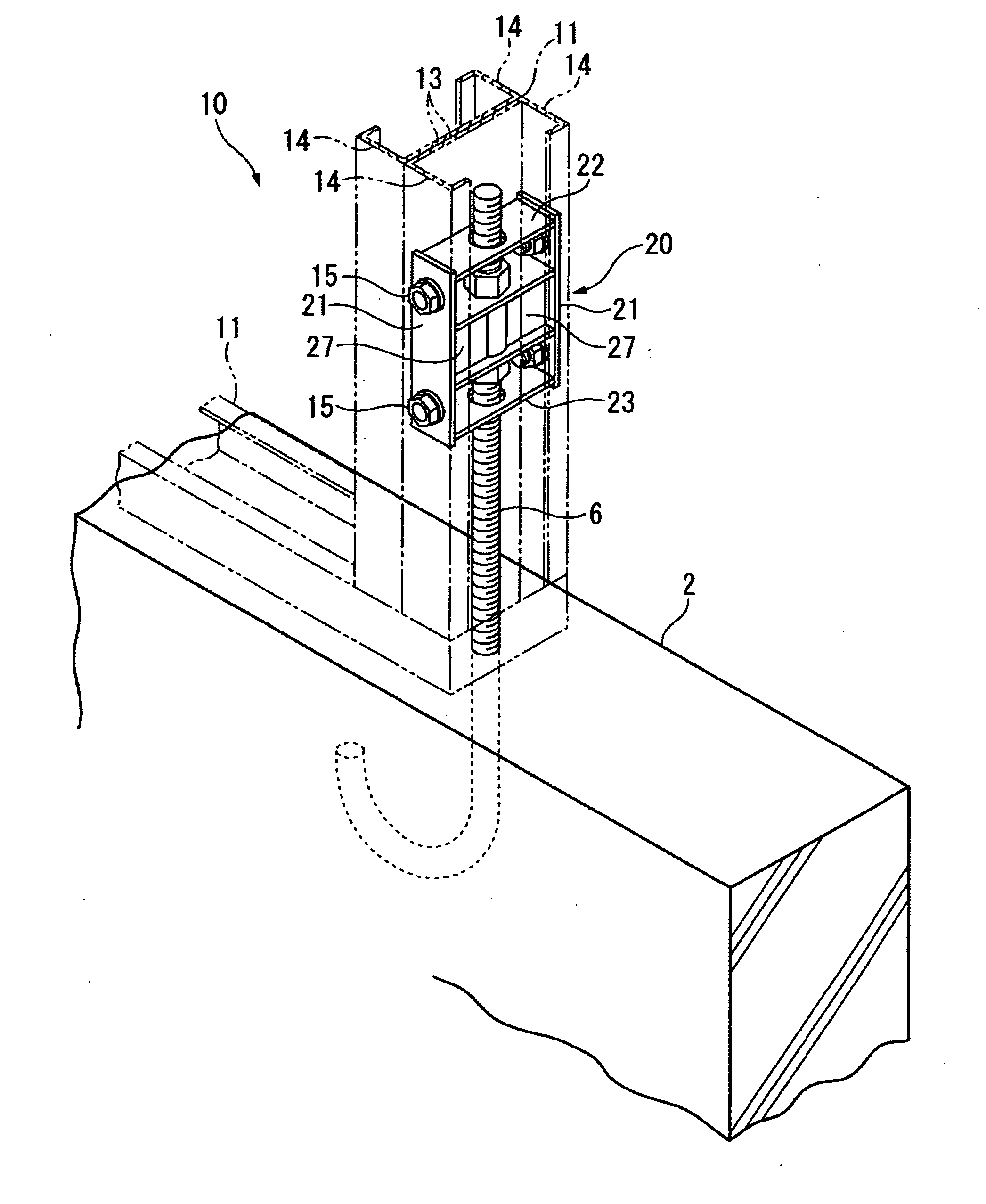
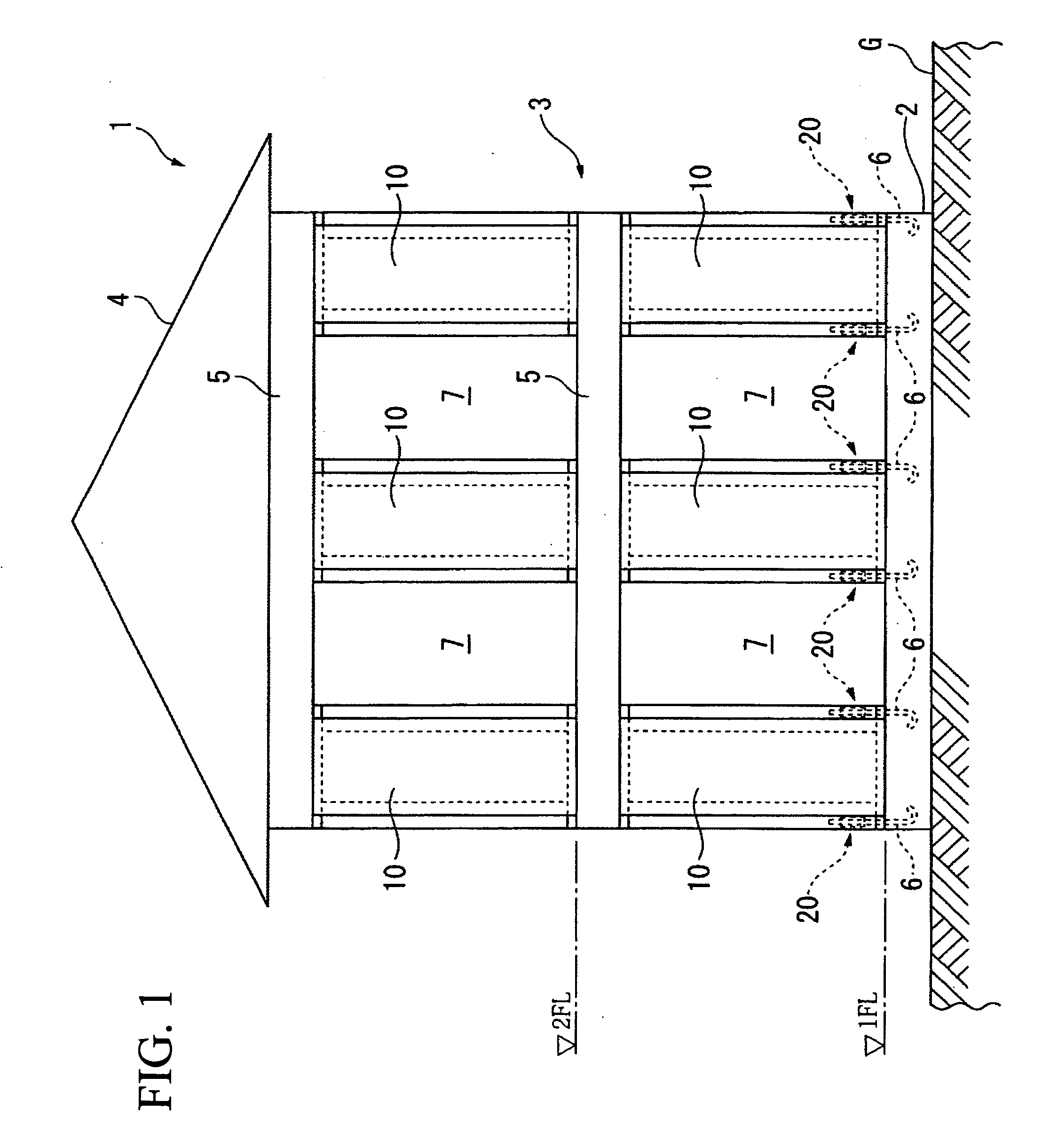
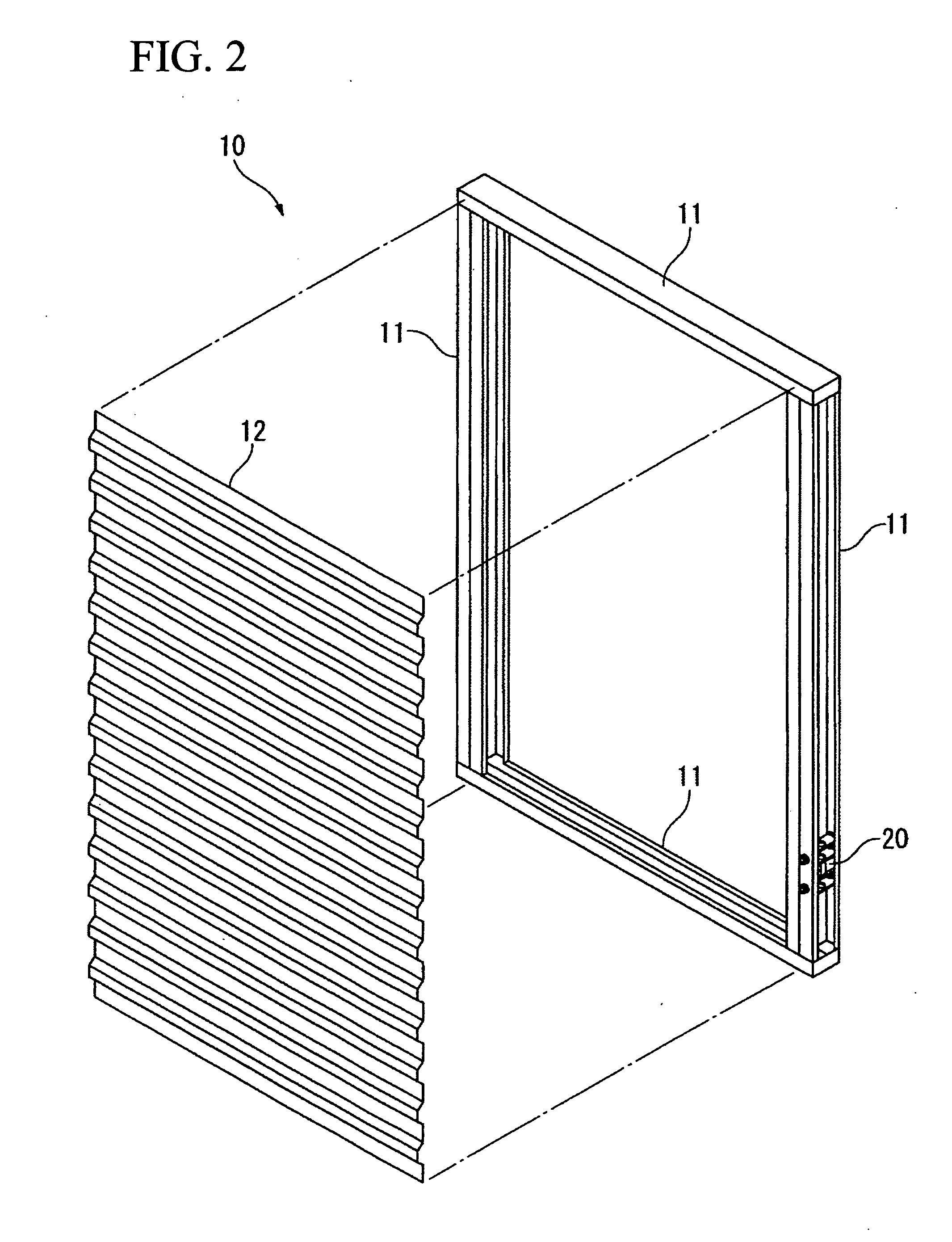
[0110]FIG. 1 is a front view showing the schematic construction of a building 1, which is constructed by a wood frame construction method, according to this embodiment. FIG. 2 is an exploded perspective view of a bearing wall 10 of the building 1 that is constructed by a wood frame construction method. FIG. 3 is a perspective view showing a connection portion between the bearing wall 10 and a foundation 2.
[0111]In FIGS. 1 to 3, the building 1, which is constructed by a wood frame construction method, is a two-story house including a foundation 2 that is constructed on the ground G and is made of reinforced concrete, a building body 3 that is fixed to the foundation 2, and a roof 4 that is provided to cover an upper portion of the building body 3.
[0112]The building body 3 includes a plurality of bearing walls 10 that is provided on floor, beams 5 that are provided at positions corresp...
second embodiment
[0134]A second embodiment of the present invention will be described below with reference to FIGS. 8 to 10.
[0135]FIGS. 8 to 10 are perspective views showing a part of a building including a metal joint according to this embodiment of the present invention.
[0136]In FIGS. 8 to 10, metal joints 50 are mounted on a column leg of a column 51 that is installed on a building foundation 2, and exert a damping effect by the rocking or rise of the column 51. The metal joint 50 has substantially the same construction as each of the metal joints 20, 30, and 40 according to the first embodiment. The metal joint includes a cylindrical steel member 52 that is a first connecting part connected to an anchor bolt 6, that is, an anchor member which is fixed to the building foundation 2 and extends upward; a fixing piece 53 that is a second connecting part connected to the column 51; and a pair of damper steel plates 54 that is damping members joined to the cylindrical steel member 52 and the fixing pi...
third embodiment
[0138]A third embodiment of the present invention will be described below with reference to FIGS. 11 and 12A to 12C.
[0139]FIG. 11 is a perspective view showing a part of a building including a metal joint according to this embodiment.
[0140]In FIG. 11, metal joints 60 are mounted to the ends of the beams 62 at column-beam joint portions 63 where a column 61 of a building is joined to beams 62, and exert a damping effect by the expansion and contraction of upper and lower flanges 64 that are caused by the bending of the beams 62. The metal joint 60 has substantially the same construction as each of the metal joints 20, 30, 40, and 50 according to the first and second embodiments. The metal joint includes a cylindrical steel member 65 that is a first connecting part connected to an anchor bolt 6, that is, an anchor member which is fixed to the column 61 or the end of each of the beams 62 that face each other with the column 61 interposed therebetween; a fixing piece 66 that is a second...
PUM
 Abstract
Description
Claims
Application Information
 - R&D
- Intellectual Property
- Life Sciences
- Materials
- Tech Scout
- Unparalleled Data Quality
- Higher Quality Content
- 60% Fewer Hallucinations
Browse by: Latest US Patents, China's latest patents, Technical Efficacy Thesaurus, Application Domain, Technology Topic, Popular Technical Reports.
© 2025 PatSnap. All rights reserved.Legal|Privacy policy|Modern Slavery Act Transparency Statement|Sitemap|About US| Contact US: help@patsnap.com


