

Particle sensor
a particle sensor and sensor technology, applied in the field of particle sensors, can solve the problems of limited measurement accuracy, and achieve the effects of improving the time resolution of measurement, reducing the sensitivity of particle sensors, and reducing the cost of measuremen
Inactive Publication Date: 2011-05-12
ROBERT BOSCH GMBH
View PDF2 Cites 7 Cited by
- Summary
- Abstract
- Description
- Claims
- Application Information
AI Technical Summary
Benefits of technology
[0007]Because of the small thickness of the diaphragm, its proportion of the total heated mass is advantageously decreased, whereby the proportion of the particles of the total heated mass is in turn proportionally increased and a calorimetric determination of the particle quantity is made possible. The precision of the particle sensor may in turn be improved and the cross-sensitivity of the particle sensor in relation to environmental influences such as moisture may be decreased.
[0032]Since a rapid temperature control of the diaphragm is possible, accumulated particles may be removed not only completely, but rather even to the extent that only a defined residue remains, in particular by heating, while simultaneously measuring the electrical conductivity. In other words, the accumulated particles may be partially removed in such a way that a minimum amount of particle bridges is maintained between the measuring electrodes. In this way, a minimum amount of particle bridges between the measuring electrodes and thus an established electrical basic conductivity and an established electrical basic resistance may be maintained. This has the advantage that a renewed particle accumulation may continue to be measured immediately via a change in electrical conductivity or a change in electrical resistance, without conductivity bridges first having to form between the measuring electrodes, which may be time-consuming in particular in the case of small particle concentrations.
Problems solved by technology
The precision of the measurement is typically limited, in particular after the regeneration and in the case of detection of small particle quantities, because particle bridges must first form between the measuring electrodes for the conductivity measurement.
Method used
View moreImage
Smart ImageViewing Examples

Examples
Embodiment Construction
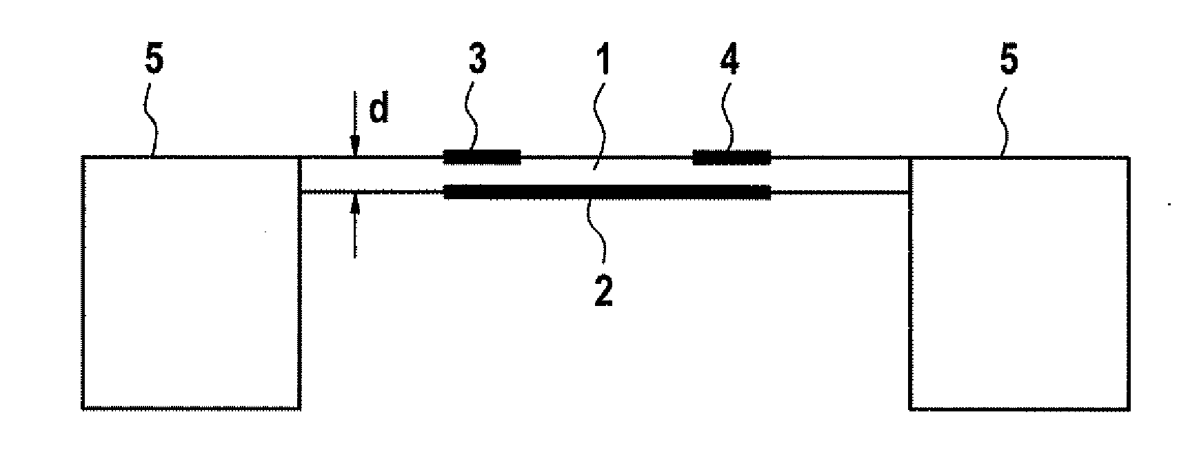
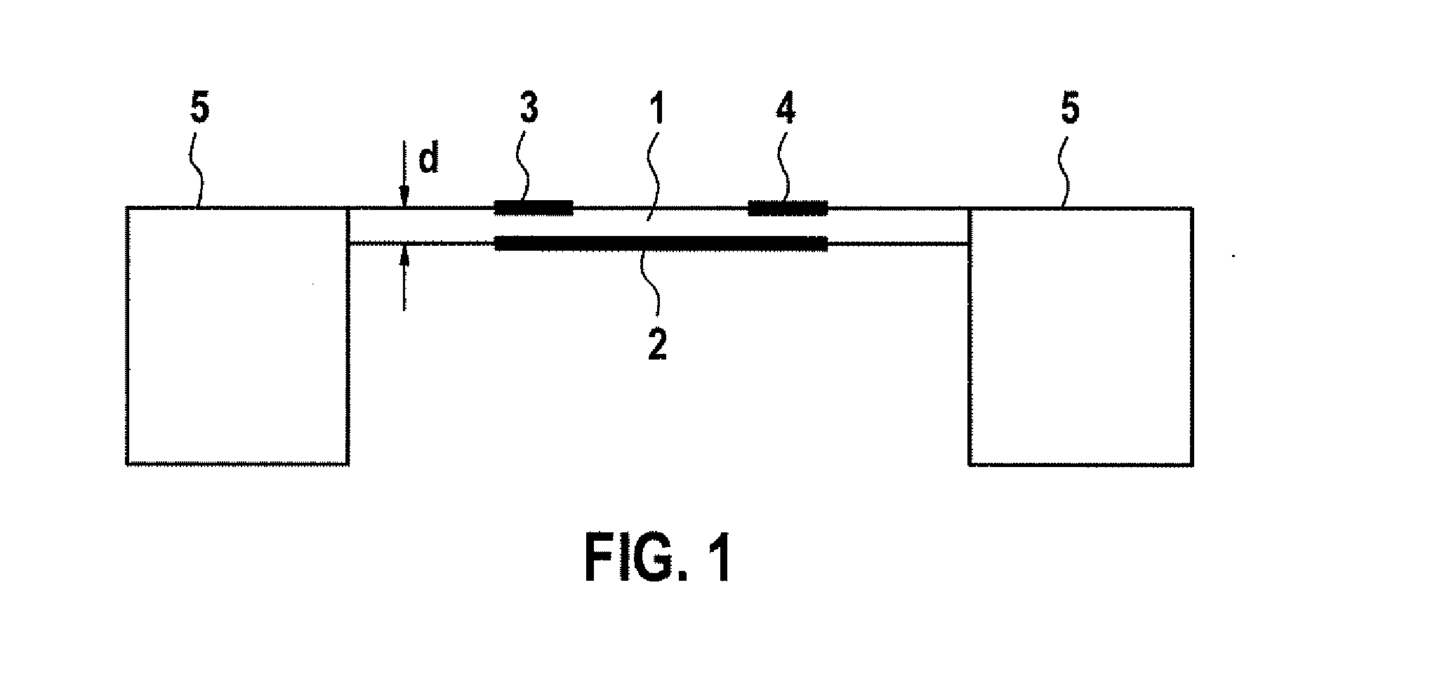
[0035]FIG. 1 shows that the particle sensor includes a diaphragm 1, a diaphragm heater 2 situated on diaphragm 1, and two measuring electrodes 3, 4 situated on diaphragm 1, for the electrical conductivity measurement. Diaphragm heater 2 and measuring electrodes 3, 4 are situated on diametrically opposing sides of diaphragm 1 in the specific embodiment shown. FIG. 1 further shows that diaphragm 1 is suspended by a substrate 5 on two diametrically opposing points.
Login to View More PUM
 Abstract
A particle sensor including a diaphragm, a diaphragm heater, and at least two measuring electrodes situated on the diaphragm, for electrical conductivity measurement, the diaphragm having a thickness of less than or equal to 50 μm, in order to allow a calorimetric particle quantity determination.
Description
FIELD OF THE INVENTION[0001]The present invention relates to a particle sensor and a method for the operation thereof.BACKGROUND INFORMATION[0002]In addition to optical methods for particle measurement, particle sensors are known, which measure the particle content in an exhaust gas via a conductivity measurement of particles accumulated on a surface between two measuring electrodes. In order to minimize the influence of condensed moisture on the conductivity, for example, these conductivity measurements are performed at a higher, constant temperature. Then, such particle sensors are periodically regenerated by thermal and / or electrical methods, in which accumulated particles are removed by so-called “burn off.”[0003]The precision of the measurement is typically limited, in particular after the regeneration and in the case of detection of small particle quantities, because particle bridges must first form between the measuring electrodes for the conductivity measurement.[0004]German...
Claims
Login to View More Application Information
Patent Timeline
 IPC IPC(8): G01N25/18G01R27/08
CPCG01N15/0656G01N27/18G01N27/04
InventorKRAUSS, ANDREASFUCHS, TINO
OwnerROBERT BOSCH GMBH