Jet grouting device with rotating roller bearing within casing pipe and rotating pipe

a technology of rotating roller bearing and grouting device, which is applied in the direction of bulkheads/piles, construction, foundation engineering, etc., can solve the problems of not being suitable for the purpose, hammering the milling or drilling operation,

Inactive Publication Date: 2011-05-12
SSESCO INC
View PDF31 Cites 29 Cited by
  • Summary
  • Abstract
  • Description
  • Claims
  • Application Information

AI Technical Summary

Benefits of technology

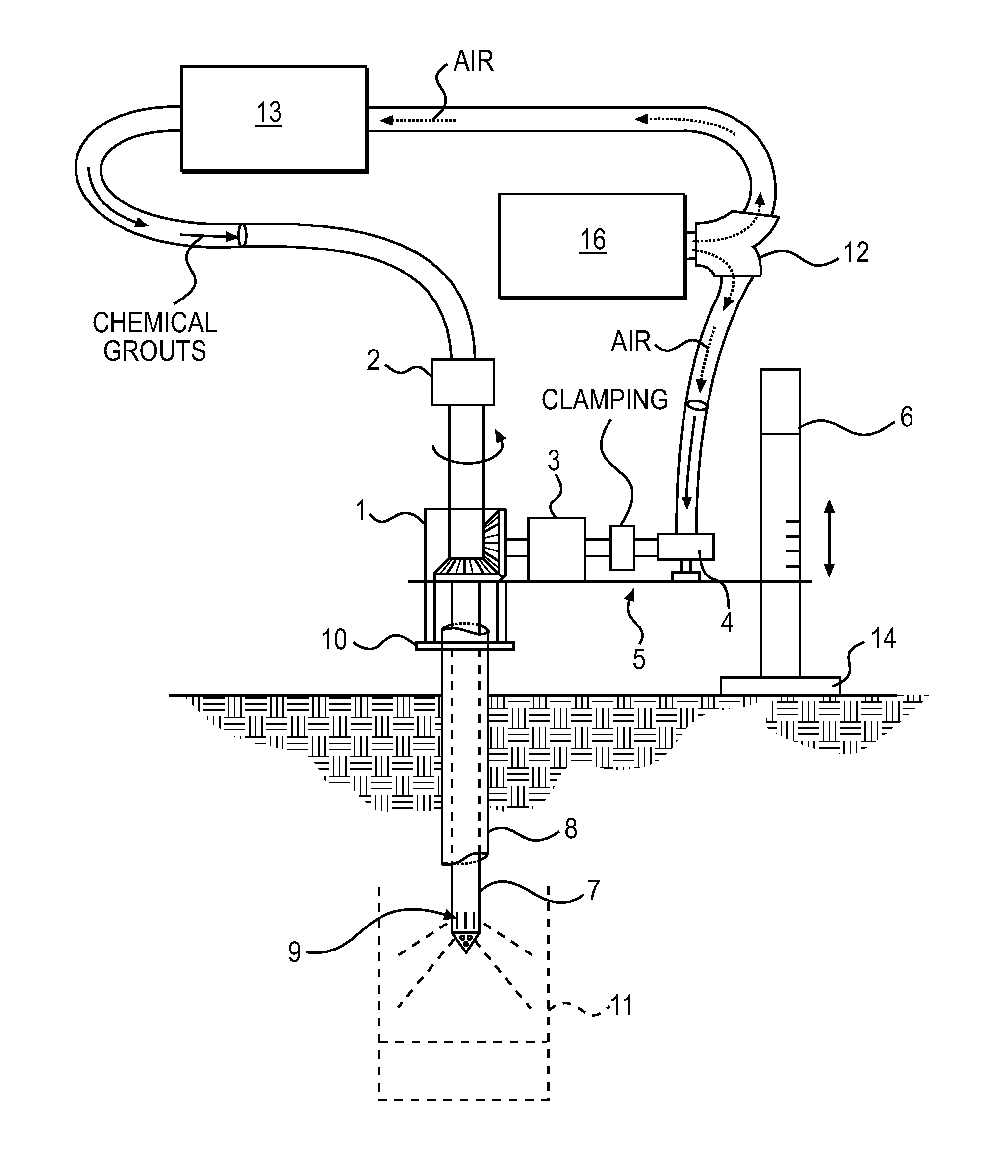
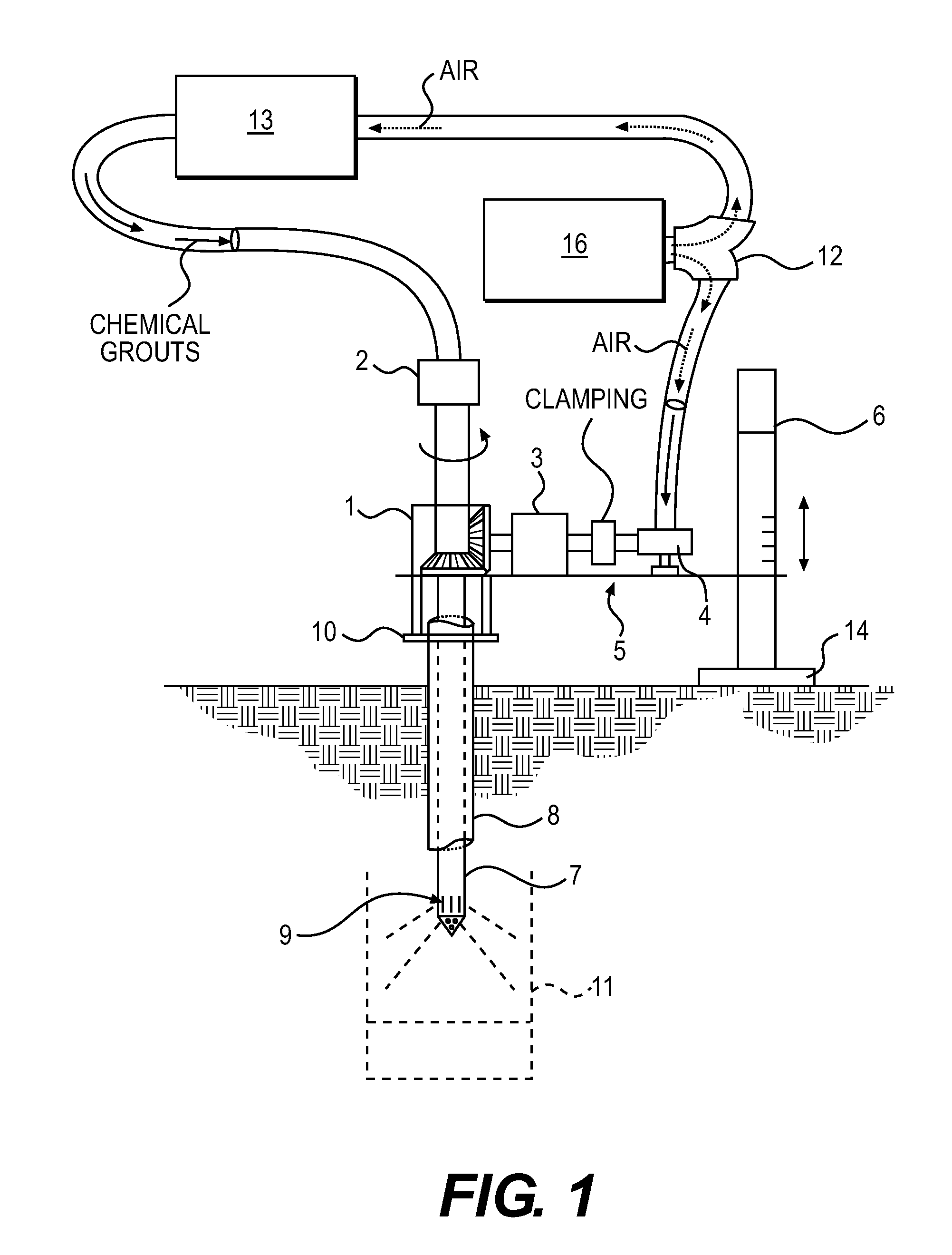
[0029]The present invention relates to a portable jet grouting device for stabilizing subsurface ground formations which includes drilling in the location of the unstable ground and injecting under high pressure a grouting material which hardens to fill voids and force the grouting material out around the end of a casing pipe through a spray nozzle. The device is small and can be operated by two persons and by the devices design it may be used in very confined areas, for example subway tunnels, sewers, underground parking garages, residential basements, natural caves, elevator shafts and remote railroad locations. Accordingly, there is a need for less heavy and large jet grouting machines in which simplicity and transportability is a must.

Problems solved by technology

Thus, the ball begins to spin within the ball seat 2 thus hampering the milling or drilling operation.
Furthermore, even though these innovations may be suitable for the specific individual purposes to which they address, accordingly, they would not be suitable for the purposes of the present invention as heretofore described.

Method used


Image

  • Jet grouting device with rotating roller bearing within casing pipe and rotating pipe
  • Jet grouting device with rotating roller bearing within casing pipe and rotating pipe
  • Jet grouting device with rotating roller bearing within casing pipe and rotating pipe

Examples


Embodiment Construction

[0038]The present invention is directed to a “Jet Grouting Device”. More specifically, the unique feature of the design is that the jet grouting operation is accomplished with minimal equipment and size providing multiple uses in compact, remote or confined areas eliminating the need for less portable and larger heavy equipment.

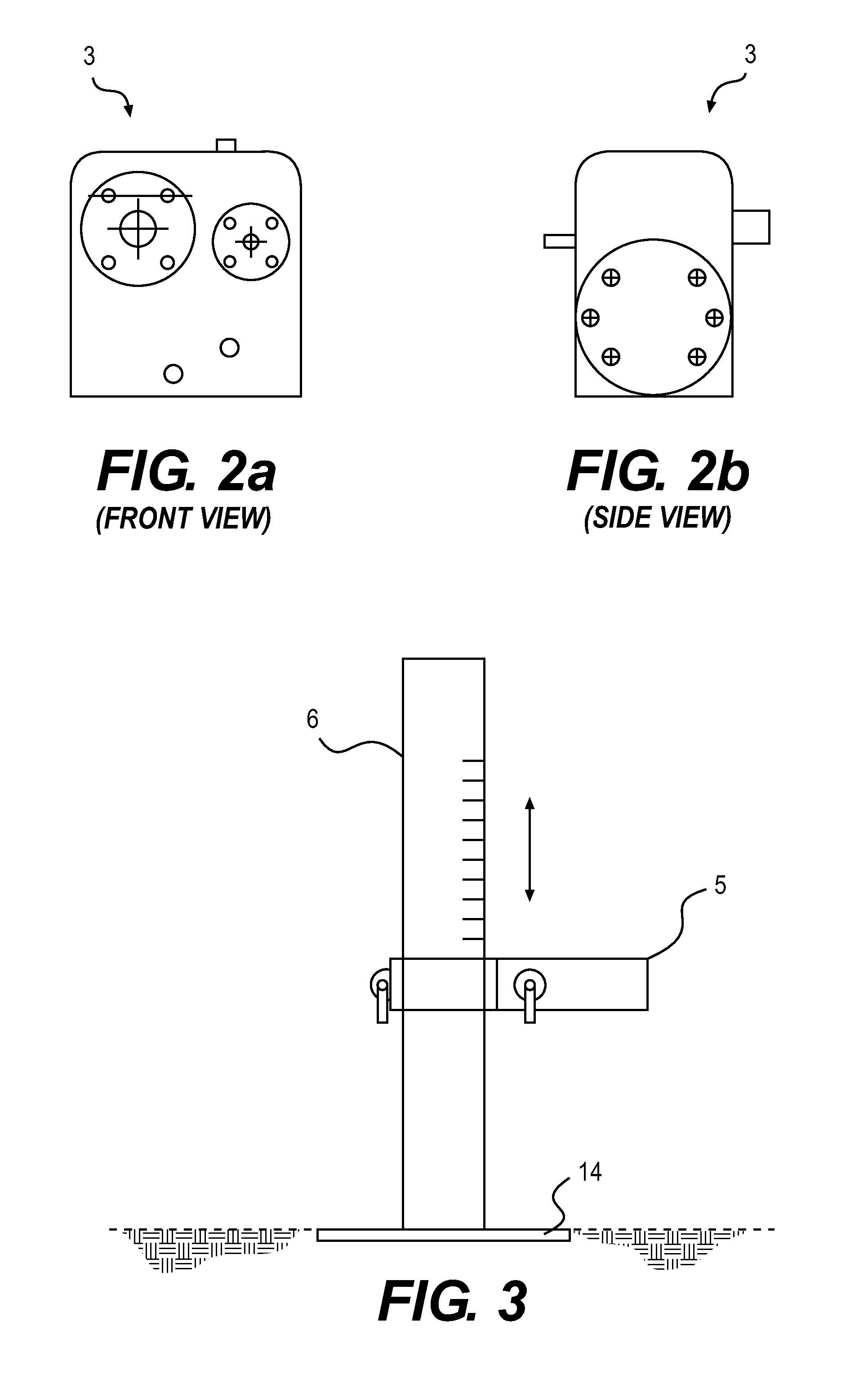
[0039]FIGS. 1 and 4 illustrate the operating position of the jet grouting device according to the present invention. The jet grouting device has a stand (6) which is generally supported by a floor base (14) on the ground and a shelf (5) which is adjustable vertically up or down. Optionally, a pneumatic, electric motor or hand crank can be used for lifting and lowering shelf (5). An air motor (4) is attached to the shelf by bolts or other means in several places. The output shaft of the air motor (4) is clamped to a gear speed reducer (3) also mounted to shelf (5) shown in FIG. 4. As shown in FIG. 1, a 90° degree or right angle gear coupling (1) are attached t...


PUM


Abstract

A high pressure jet grouting device generally employed with a portable stand comprised of a vertically adjustable shelf forming a platform for attaching an air motor, reduction gearing box and a releasable right angle gear box. High pressure air is pumped to the air motor and a grouting pump, the air pressure is used to turn the right angle gear and a rotatable pipe inside a casing pipe. The grouting material under pressure from the air compressor is pumped through a hose to a swivel connection on the end portion of a rotating pipe to inject the grout into the ground from a spray nozzle located at the opposite end of the rotating pipe inserted in the ground. A rotating roller bearing is provided between casing pipe and the rotating pipe. The device is small and does not require a heavy drill rig as the drilling operation is separately performed from the grouting process.

Description

CROSS REFERENCE TO RELATED APPLICATION[0001]This application claims the benefit of Provisional Patent Application No. 61 / 258,617 filed on Nov. 6, 2009, in the United States Patent & Trademark Office, the disclosure of which is incorporated herein by reference.STATEMENT OF FEDERALLY SPONSORED RESEARCH / DEVELOPMENT[0002]Not ApplicableBACKGROUND OF THE INVENTION[0003]Jet grouting has been used to stabilize contaminated soils, create groundwater barriers and to underpin distressed foundations. Jet grout construction uses a rotating and rising drill rod with small nozzles that direct the grout horizontally to form columns of soil crete or soil-cement and is the only type of grouting that is capable of treating all types of soils from clays to gravel. Jet grouting is also useful in grouting isolated zones of soil and for grouting around and below buried utilities. Jet grouting is a general term describing various construction techniques used for ground modification or ground improvement. G...

Claims


Application Information

Patent Timeline
Patent Type & Authority Applications(United States)
IPC IPC(8): E02D3/12
CPCE02D3/12
Inventor PLAHERT, THOMAS
Owner SSESCO INC
Why Eureka
Try Eureka