Distraction pins for fluid aspiration

a technology of dissection pins and fluid aspiration, which is applied in the direction of osteosynthesis devices, applications, manufacturing tools, etc., can solve the problems of increasing the procedure time and exposing the patient to more risks

Inactive Publication Date: 2011-05-12
SPINESMITH PARTNERS
View PDF35 Cites 34 Cited by
  • Summary
  • Abstract
  • Description
  • Claims
  • Application Information

AI Technical Summary

Benefits of technology

[0005]This invention provides a solution to one or more of the problems and / or deficiencies described in the background.

Problems solved by technology

This process increases the procedure time and subjects the patient through more risk.

Method used


Image

  • Distraction pins for fluid aspiration
  • Distraction pins for fluid aspiration
  • Distraction pins for fluid aspiration

Examples


Embodiment Construction

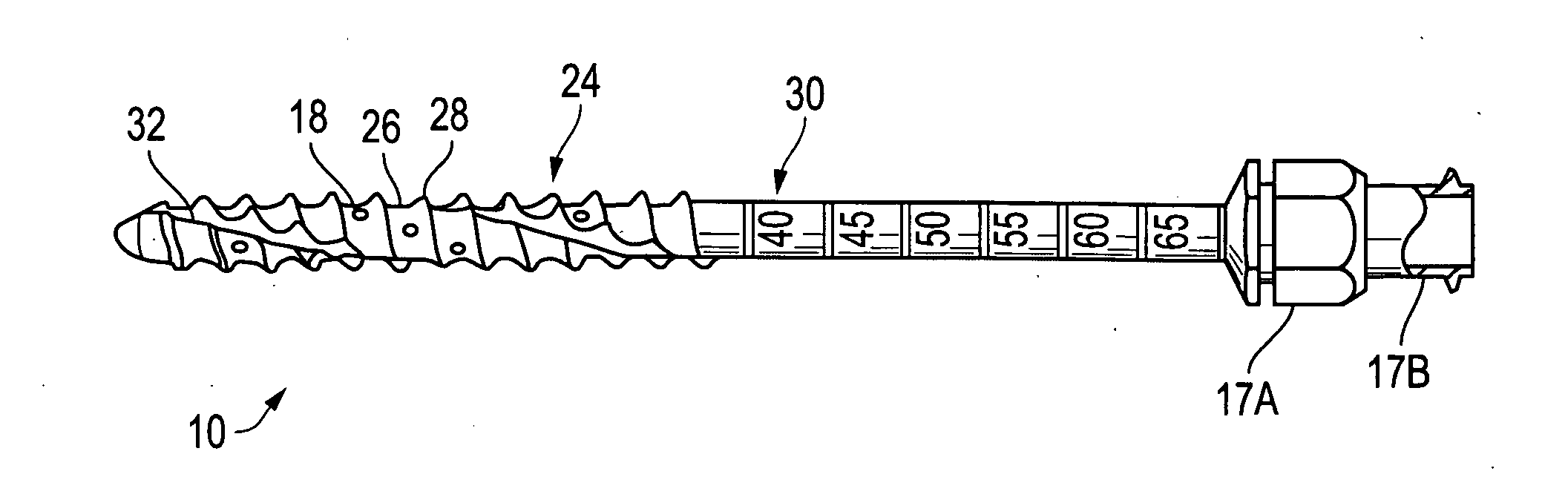
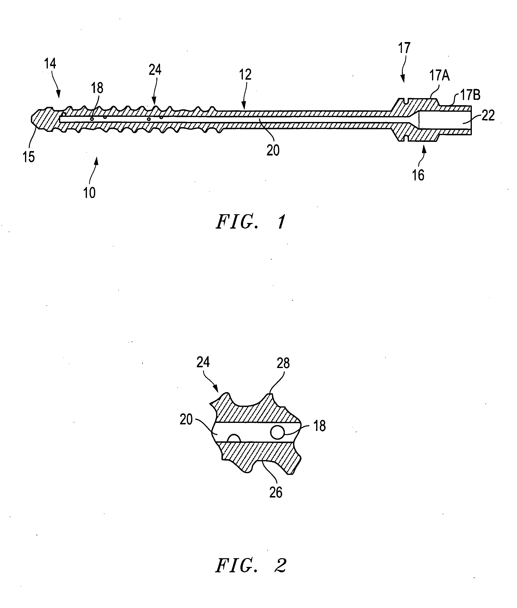
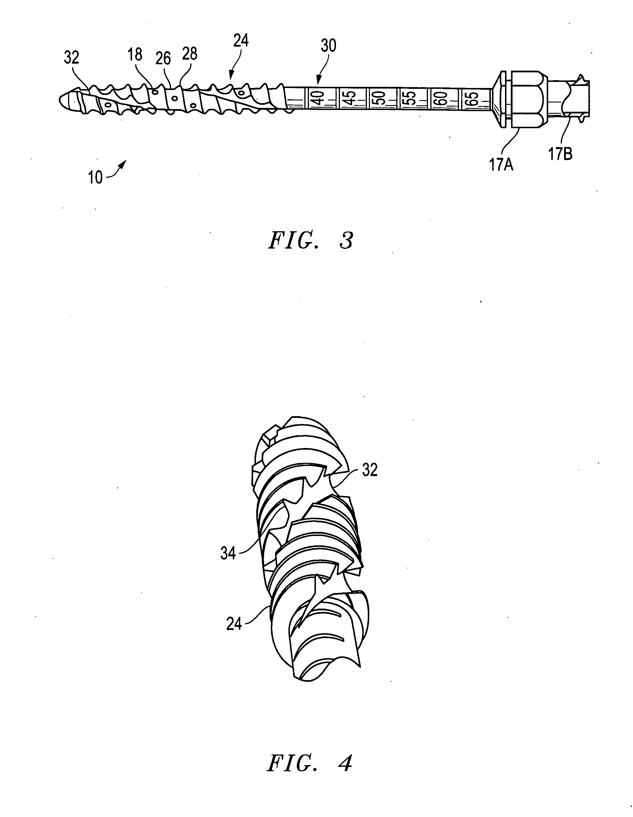
[0022]Distraction pins may be used to facilitate distraction and deliver / aspirate fluid. Each distraction pin includes a channel disposed through the distraction pin shaft such that the channel is in fluid communication with the bone marrow. The channel facilitates the extraction or delivery of fluids, including bone marrow, through the distraction pin. The channel diameter may vary as a function of the concentration of fluid to be obtained or delivered.

[0023]The distraction pin may include other features, such as threading to stabilize the distraction pin, or fenestrations to facilitate the extraction or delivery of fluids. Fenestration holes may be strategically placed to localize where the fluid is drawn from and to avoid drawing peripheral blood from higher positions within the bone and from outside the cortical shell.

[0024]Cutting flutes may also be placed at the distal end of the distraction pin. These cutting flutes may be strategically placed to prevent inflow of peripheral ...


PUM

PropertyMeasurementUnit
lengthaaaaaaaaaa
lengthaaaaaaaaaa
diameteraaaaaaaaaa

Abstract

A distraction pin for aspiration of a bone fluid and marrow. The pin includes an elongate metallic shaft of generally uniform diameter having a proximate end. The proximate end of the shaft includes an adaptor (attachment means) and a longitudinal bore extending from the distal end to the proximate end. The distal end of the shaft includes threading adapted for screwing the shaft into bone. The distal end also includes at least two fenestrations transverse to the longitudinal bore.

Description

[0001]This application claims priority to U.S. Provisional Application Ser. No. 61 / 258,994, filed Nov. 6, 2009, which is incorporated in its entirety herein by reference.BACKGROUND OF INVENTION[0002]This invention pertains to distraction pins capable of fluid aspiration.[0003]During a typical spinal surgery, two or more caspar pins are screwed into vertebral bodies. A retractor, or similar instrument, is then attached to two or more caspar pins, allowing a surgeon to distract the vertebral bodies to accommodate a surgical procedure (e.g. spinal fusion, disc replacement, etc.). Distraction pins are typically used in cervical procedures, but may also be used in other lumbar or orthopedic procedures.[0004]Recent studies have shown that there are a high percentage of stem cells present in the bone marrow in the cervical vertebral bodies of the spine. However, in order to remove this bone marrow, a surgeon must create a separate opening through the vertebral body and use a syringe or oth...

Claims


Application Information

Patent Timeline
Patent Type & Authority Applications(United States)
IPC IPC(8): A61B10/00B23P15/52
CPCA61B10/025A61B10/0283A61B17/1655Y10T29/4998A61B2010/0258A61B2019/462A61B17/864A61B2090/062
Inventor JONES, ROBERT J.KANA, RICHARDROSSMAN, JOHN B.
Owner SPINESMITH PARTNERS
Why Eureka
Try Eureka