System and Method for Placing a Coronary Stent at the Ostium of a Blood Vessel

a technology of coronary artery and stent, which is applied in the field of balloon catheters, can solve the problems of a restnosis or, perhaps, a collapse of the weakened blood vessel, and the need for limited insertion of the sten

Inactive Publication Date: 2011-05-12
SCHATZ RICHARD A
View PDF16 Cites 35 Cited by
  • Summary
  • Abstract
  • Description
  • Claims
  • Application Information

AI Technical Summary

Benefits of technology

[0011]For an operation of the present invention, a guide wire is pre-positioned in the vasculature of a patient, with the guide wire extending into the ostium of the blood vessel. The balloon / stent catheter is then advanced over the guide wire, inside the guiding catheter. This continues until the distal end of the balloon / stent catheter is near the ostium. At that point, either the balloon / stent catheter is advanced through the guiding catheter in a distal direction, or the guiding catheter is withdrawn in a proximal direction to reconfigure the barrier member from its first configuration, and into its second configuration. The balloon / stent catheter is then further advanced, with the array in the second configuration, for use of the barrier to prevent an advancement of the catheter into the ostium, after the stent has been properly positioned in the ostium. The balloon is then inflated to deploy and place the stent in the ostium. Next, the balloon is deflated, and the catheter, less the stent, is withdrawn into the guiding catheter. This withdrawal also returns the barrier member to its first configuration. The system is then withdrawn from the vasculature.

Problems solved by technology

After an angioplasty procedure, it is well known that there is always the possibility of a restenosis or, perhaps, a collapse of the weakened blood vessel at the site of the procedure.
In this latter case, not only does the stent need to be properly inserted into the ostium, its insertion must be limited to ensure a proper placement of the stent.

Method used


Image

  • System and Method for Placing a Coronary Stent at the Ostium of a Blood Vessel
  • System and Method for Placing a Coronary Stent at the Ostium of a Blood Vessel
  • System and Method for Placing a Coronary Stent at the Ostium of a Blood Vessel

Examples


Embodiment Construction

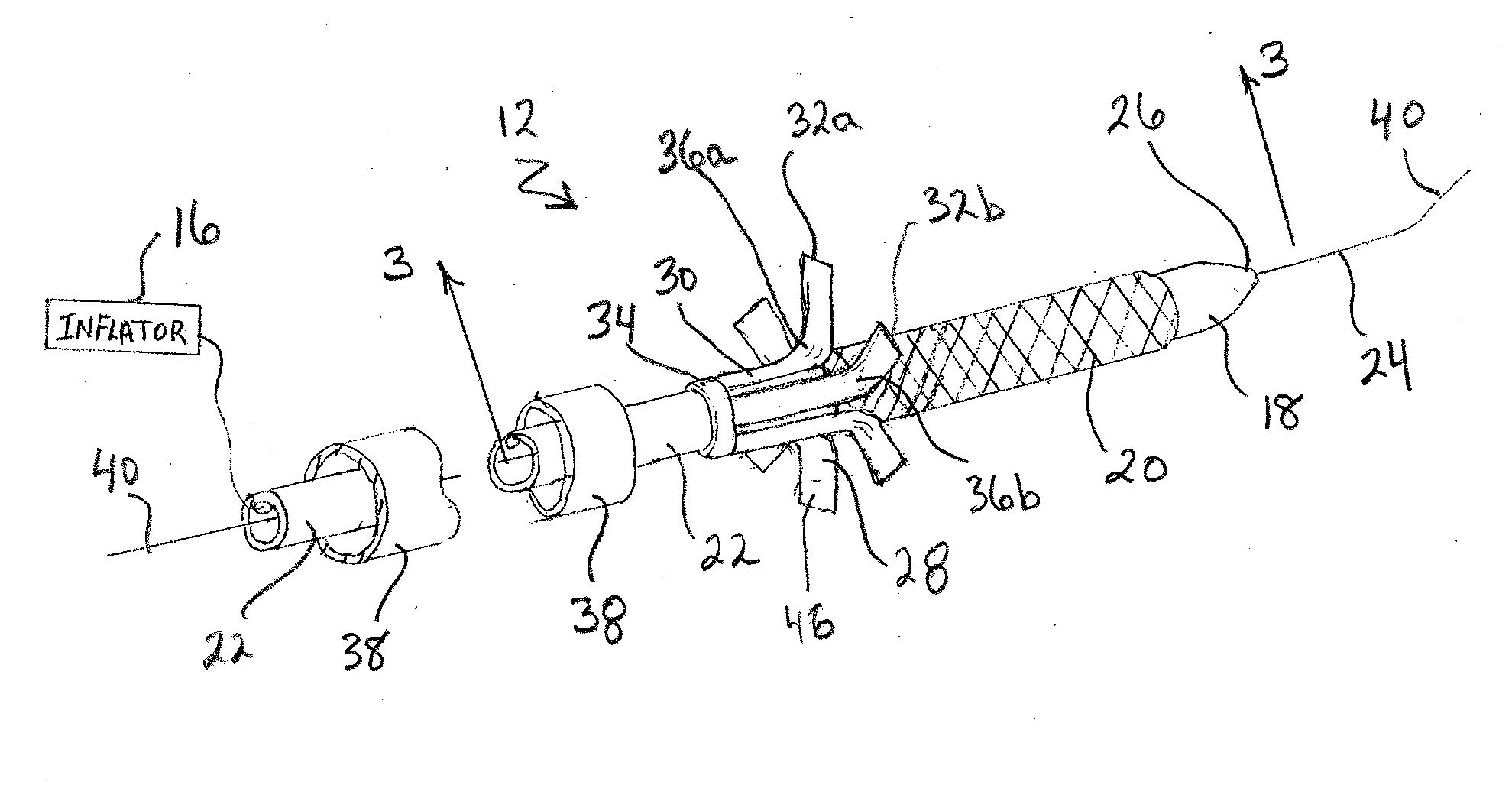
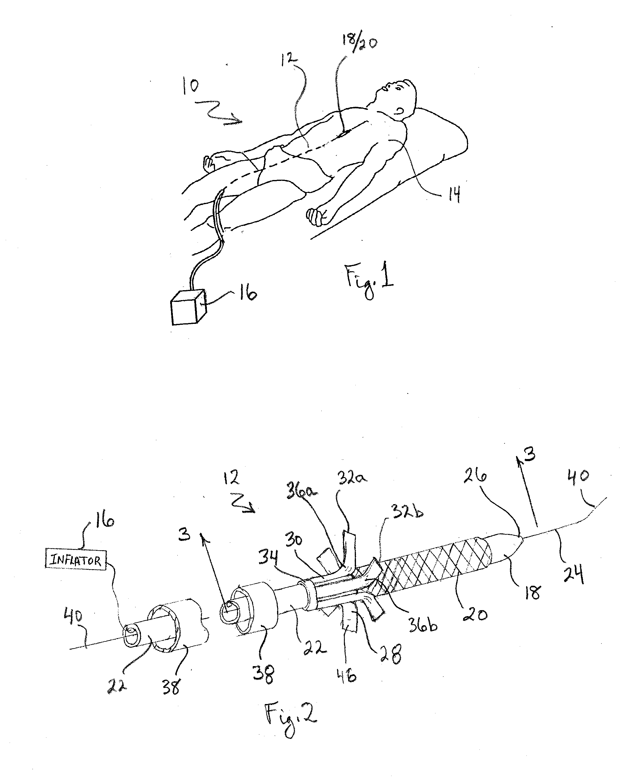
[0023]Referring initially to FIG. 1 a system for delivering a stent to the ostium of a blood vessel in accordance with the present invention is shown and is generally designated 10. As shown, the system 10 includes a balloon / stent catheter 12 that is being advanced into the vasculature of a patient 14. Once the catheter 12 has been properly placed in the vasculature, an inflator 16 is activated to inflate a balloon 18. With this inflation of the balloon 18, a stent 20, that is positioned (crimped) onto the balloon 18, will expand. The stent 20 will then be left at the ostium of a blood vessel after the catheter 12 is withdrawn from the vasculature. Structural details of the balloon / stent catheter 12 will be best appreciated with reference to FIG. 2.

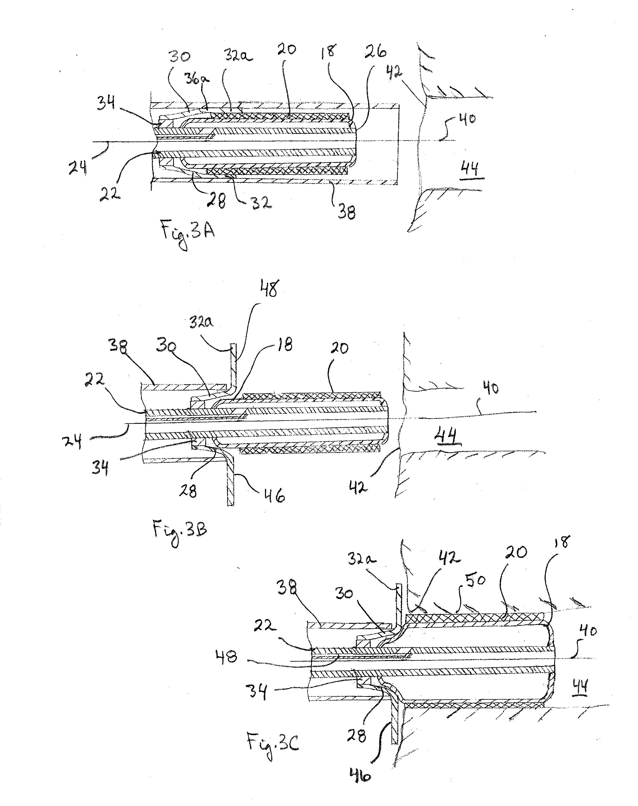
[0024]In FIG. 2 it will be seen that the balloon / stent catheter 12 includes a shaft 22 defining a longitudinal axis 24. For the present invention, the balloon 18 is affixed to the shaft 22 at a location immediately proximal the distal end...


PUM


Abstract

A system and method are provided that use a balloon/stent catheter for placing a stent at the ostium of a blood vessel. Included is a barrier member that is attached to the catheter at a location proximal the balloon. In use, the barrier member is reconfigured, prior to insertion of the balloon/stent portion of the catheter through the ostium. With this reconfiguration, a barrier (array) is established that limits advancement of the catheter into the blood vessel to ensure proper placement of the stent at the ostium.

Description

[0001]This application claims the benefit of U.S. Provisional Patent Application Ser. No. 61 / 259,871, filed Nov. 10, 2009.FIELD OF THE INVENTION[0002]The present invention pertains generally to intravascular catheter systems. More particularly, the present invention pertains to balloon catheters that are used to place stents in the vasculature of a patient. The present invention is particularly, but not exclusively, useful as a stent delivery system for placing a stent at the ostium of a blood vessel, wherein the catheter incorporates a barrier (array) that limits insertion of the balloon / stent through the ostium of the blood vessel, to ensure a proper placement of the stent at the ostium.BACKGROUND OF THE INVENTION[0003]After an angioplasty procedure, it is well known that there is always the possibility of a restenosis or, perhaps, a collapse of the weakened blood vessel at the site of the procedure. To help minimize either of these possibilities, and to hopefully avoid them altog...

Claims


Application Information

Patent Timeline
Patent Type & Authority Applications(United States)
IPC IPC(8): A61F2/84A61F2/82
CPCA61F2002/821A61F2/958
Inventor SCHATZ, RICHARD A.
Owner SCHATZ RICHARD A
Why Eureka
Try Eureka