
Crane apparatus

a technology of crane and crane body, which is applied in the field of crane apparatus, can solve the problems of inefficiency in terms of facility cost and operating cost, and need a power, and achieve the effects of reducing the scale of the power supply system, reducing the volume, and reducing the need for power

Inactive Publication Date: 2011-05-12
MITSUI ENG & SHIPBUILD CO LTD
View PDF2 Cites 23 Cited by
  • Summary
  • Abstract
  • Description
  • Claims
  • Application Information

AI Technical Summary

Benefits of technology

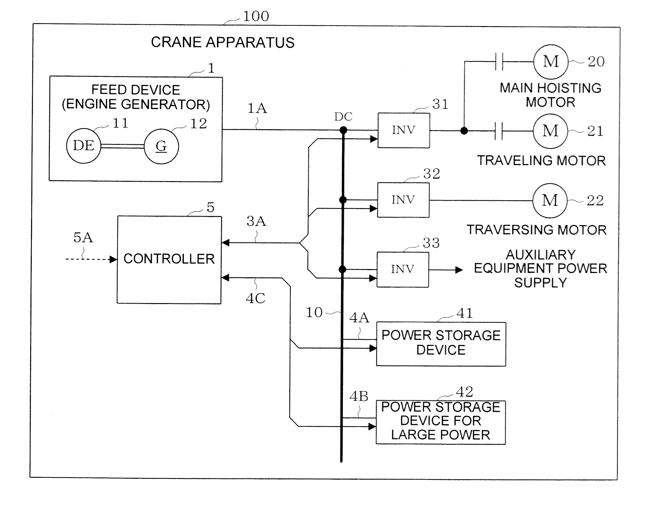
[0012]According to the present invention, the first power storage device stores part of a supply power, and in case of shortage of the supply power, discharges the storage power to compensate for the supply power. A second power storage device stores part of the supply power, and discharges the storage power at least in a cargo lifting operation by motors to compensate for the supply power. As the second power storage device, a power storage device having an output density higher than that of the first power storage device is used. This allows the second power storage device to discharge a large storage power in a short time when lifting cargo.
[0013]The same functions as those of an arrangement using only the first power storage device can be implemented by the first and second power storage devices having a smaller volume. It is consequently possible to efficiently reduce the scale of the power supply system while suppressing an increase in the scale of the power storage devices.
[0014]When a power storage device having an energy density higher than that of the second power storage device is used as the first power storage device, the first power storage device can stably discharge the storage power for a long time during a period except the period of cargo lifting operation.
[0015]The same functions as those of an arrangement using only the second power storage device can be implemented by the first and second power storage devices having a smaller volume. It is consequently possible to efficiently reduce the scale of the power supply system while suppressing an increase in the scale of the power storage devices.

Problems solved by technology

However, the operation of, e.g., lowering cargo rarely needs a power.
This makes the system scale more than the average load, resulting in inefficiency in terms of facility cost and operating cost.

Method used


Image

  • Crane apparatus
  • Crane apparatus
  • Crane apparatus

Examples


first embodiment

Operation of First Embodiment

[0062]The operation of the crane apparatus according to the first embodiment of the present invention will be described next with reference to FIG. 5. An example will he explained here in which the crane apparatus 100 lifts the container 9, performs the traversing operation, lowers and lands the container 9, travels to an end of the lane 71, and then travels perpendicularly to move to another lane 71.

[0063][Lifting Operation]

[0064]When the command 5A representing an instruction to lift the container 9 is input by an operator's operation at time T0, the controller 5 transmits the command 3A to the inverter 31 so as to instruct driving of the main hoisting motor 20. Since the main hoisting motor 20 thus rotates to start lifting the container 9, a load power 10A on the common bus 10 rises from a load power Pd used by the units of the crane apparatus 100 in the normal state to a maximum load power Pa. The controller 5 also outputs the command 4C in accordanc...

third embodiment

[0107]A crane apparatus according to the third embodiment of the present invention will be described next with reference to FIG. 11.

[0108]In the second embodiment, an example has been described in which a power supplied from the power supply device 7 of the lane 71 via the power supply cable 14 is used as the supply power 1A by a ground feed scheme. In the third embodiment, an example will be explained in which a power supplied from the power supply device of a lane is collected by a noncontact feed scheme and used as a supply power 1A by a ground feed scheme.

[0109]The electrical arrangement of the crane apparatus according to this embodiment will be described first with reference to FIG. 11.

[0110]A current collector 15 has a function of collecting, by a noncontact current collection scheme, a source power from a power supply device 7 provided in each lane 71 of a container terminal 70 via feed cables 8A laid along the lane 71. As the noncontact current collection scheme, a known te...

second embodiment

Operation of Second Embodiment

[0117]The operation of the crane apparatus according to the third embodiment of the present invention will be described next with reference to FIG. 17. An example will be explained here in which the crane apparatus 102 lifts a container 9, performs the traversing operation, lowers and lands the container 9, travels to an end of the lane 71, and then travels perpendicularly to move to another lane 71.

[0118]In the crane apparatus 102 as well, if the supply power 1A output from the feed device 1 to the bus 10 has a plus, power storage devices 41 and 42 store it as storage powers 4A and 4B example, above-described traversing from time T1 in FIG. 5, traveling from time T3, and a standby state in which no crane operation is being performed, as in the first embodiment.

[0119]When performing the lifting operation, the storage powers 4A and 40 of the power storage devices 41 and 42 are supplied to a main hoisting motor 20 via the common bus 10 and an inverter 31 ...


PUM


Abstract

A power storage device (first power storage device) (41) stores part of a supply power, and in case of shortage of the supply power, discharges the storage power to compensate for the supply power. A power storage device (second power storage device) (42) stores part of the supply power, and discharges the storage power at least in a cargo lifting operation by motors to compensate for the supply power. As the power storage device (42), a power storage device having an output density higher than that of the power storage device (41) is used. Alternatively, as the power storage device (41), a power storage device having an energy density higher than that of the power storage device (42) is used.

Description

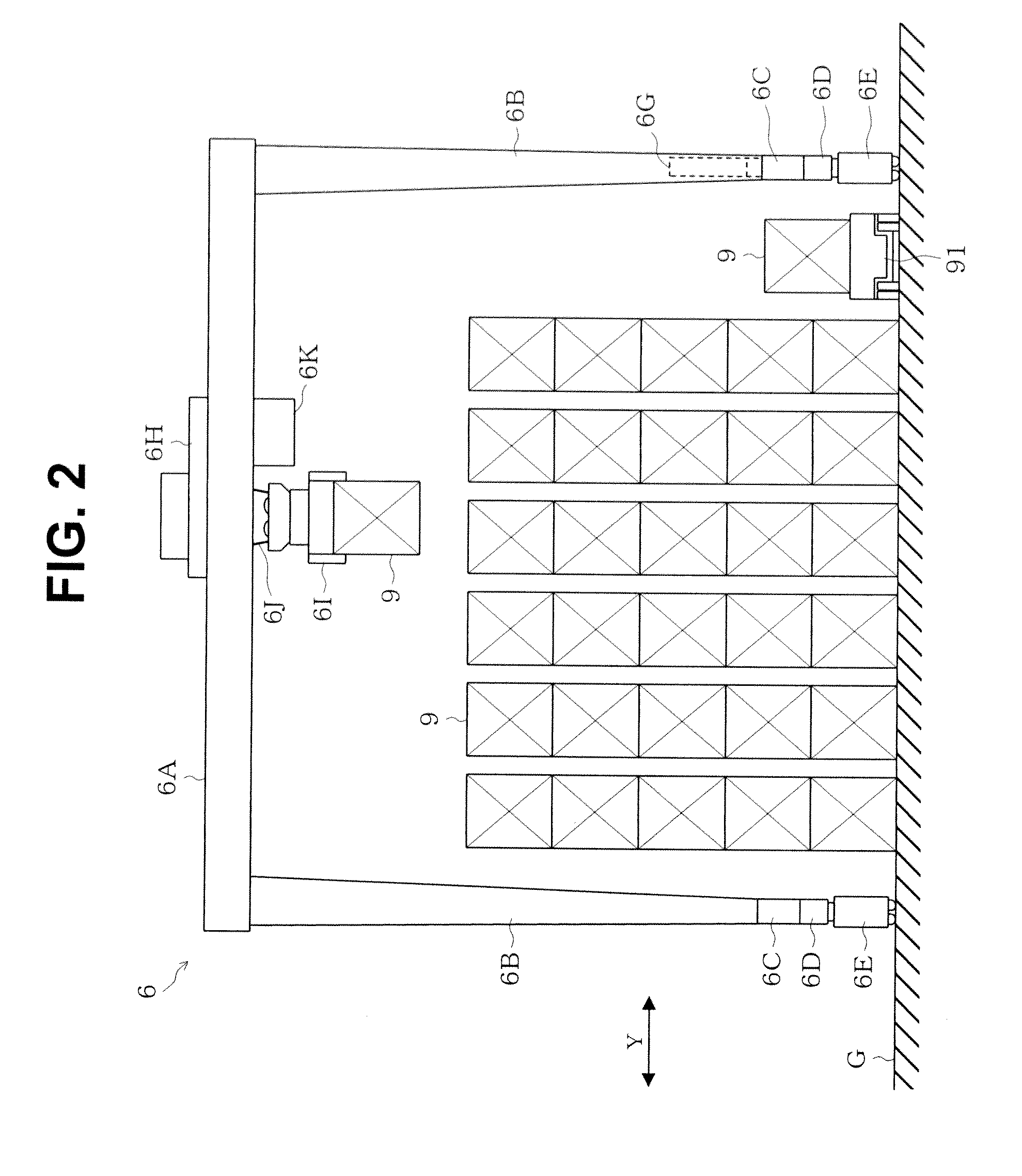
TECHNICAL FIELD [0001]The present invention relates to a crane apparatus and, more particularly, to a gantry crane apparatus for handling containers at a container terminal by driving motors.BACKGROUND ART[0002]A gantry crane apparatus for performing cargo handling to, e.g., load / unload containers on / from a ship or trailer at a container terminal lifts or lowers cargo, and also performs gantry traveling or traversing using a plurality of motors. One of schemes of supplying a power to these motors is an engine driven power generation scheme. The engine driven power generation scheme is designed to generate a necessary power using an engine generator that drives a power generator by a diesel engine, and supply the power to each motor. Another scheme of supplying a power to the motors is a ground feed scheme. The ground feed scheme is designed to install a power supply device in each of lanes partitioned in advance at a container terminal, and supply a source power from the power suppl...

Claims


Application Information

Patent Timeline
IPC IPC(8): B66C13/14G06F7/00
CPCB66C13/12B66C19/007B66C13/28B66C13/18B60L2200/40B60L50/15Y02T10/7072Y02T10/64
Inventor HARADA, HIDEKAZU
Owner MITSUI ENG & SHIPBUILD CO LTD
Learn More