Guiding an ignition spark plug in a turbomachine combustion chamber

a technology of turbomachines and ignition spark plugs, which is applied in the direction of machines/engines, burner ignition devices, lighting and heating apparatus, etc., can solve the problems of premature wear of the spark plug in the zone and guide to turn, and achieve the effect of simple, effective and inexpensiv

Inactive Publication Date: 2011-05-19
SN DETUDE & DE CONSTR DE MOTEURS DAVIATION S N E C M A
View PDF5 Cites 18 Cited by
  • Summary
  • Abstract
  • Description
  • Claims
  • Application Information

AI Technical Summary

Benefits of technology

[0012]A particular object of the invention is to provide a solution to this problem that is simple, effective, and inexpensive.
[0013]To this end, the invention provides a turbomachine combustion chamber including at least one ignition spark plug carried by an outer casing and extending in guide means carried by a wall of the chamber, the wall forming a body of revolution, the guide means comprising a tubular guide having the spark plug passing axially therethrough and mounted with axial and transverse clearance on a chimney fastened to the wall of the chamber and opening out into the chamber, wherein in order to reduce wear of the spark plug in operation, the spark plug is mounted by being fastened in a sheath, the tubular guide being slidably mounted around the sheath.
[0014]In this way, the tubular guide does not subject the spark plug to wear but instead subjects the sheath to wear, where the sheath is a part that is inexpensive and easy to replace.
[0018]The collar then forms an abutment that makes it easier to position the sheath.

Problems solved by technology

In addition, vibration, and the above-mentioned air flow tend to cause the guide to turn around the spark plug.
This gives rise to premature wear of the spark plug in its zone that makes contact with the guide.

Method used


Image

  • Guiding an ignition spark plug in a turbomachine combustion chamber
  • Guiding an ignition spark plug in a turbomachine combustion chamber
  • Guiding an ignition spark plug in a turbomachine combustion chamber

Examples


Embodiment Construction

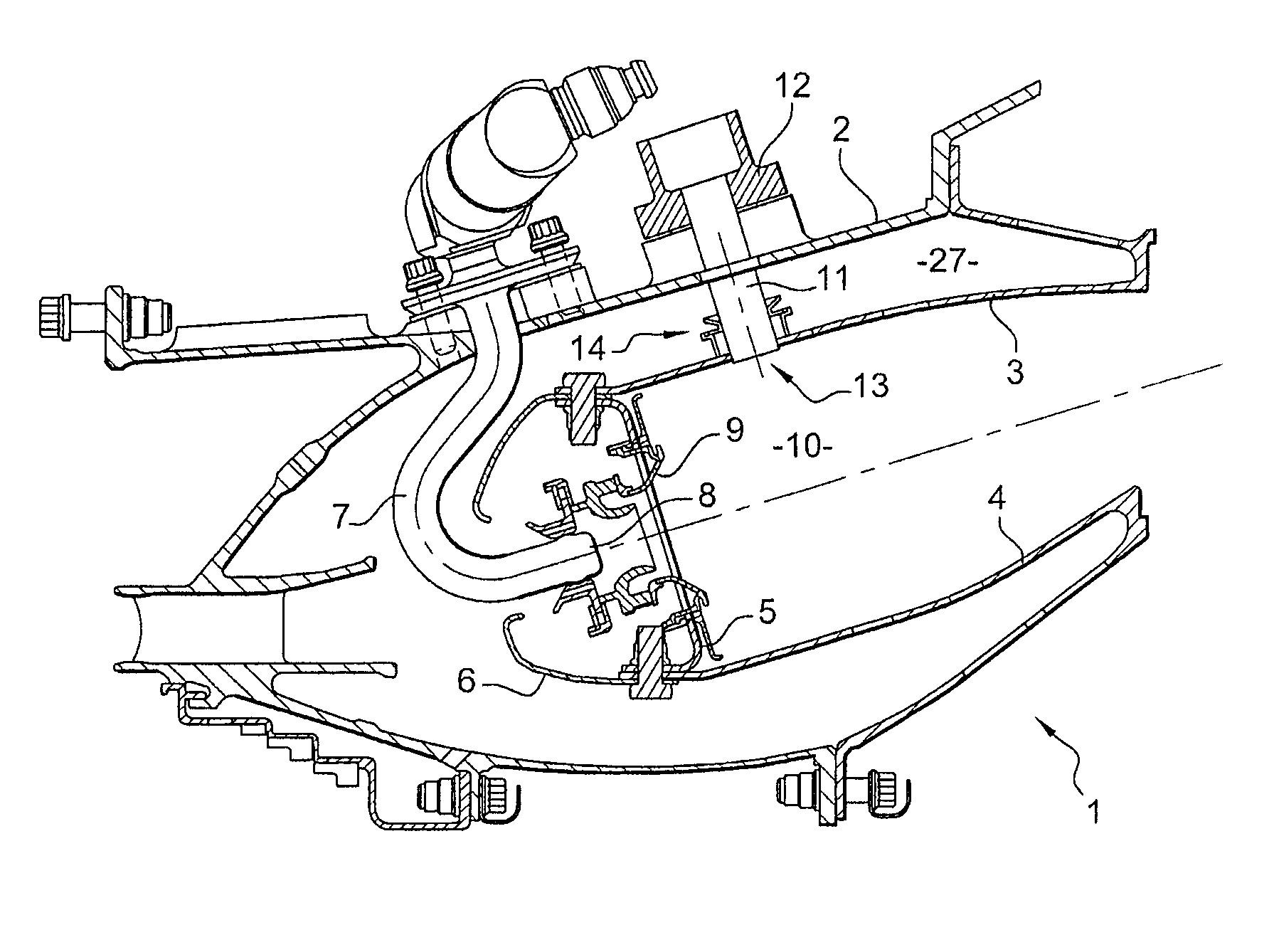
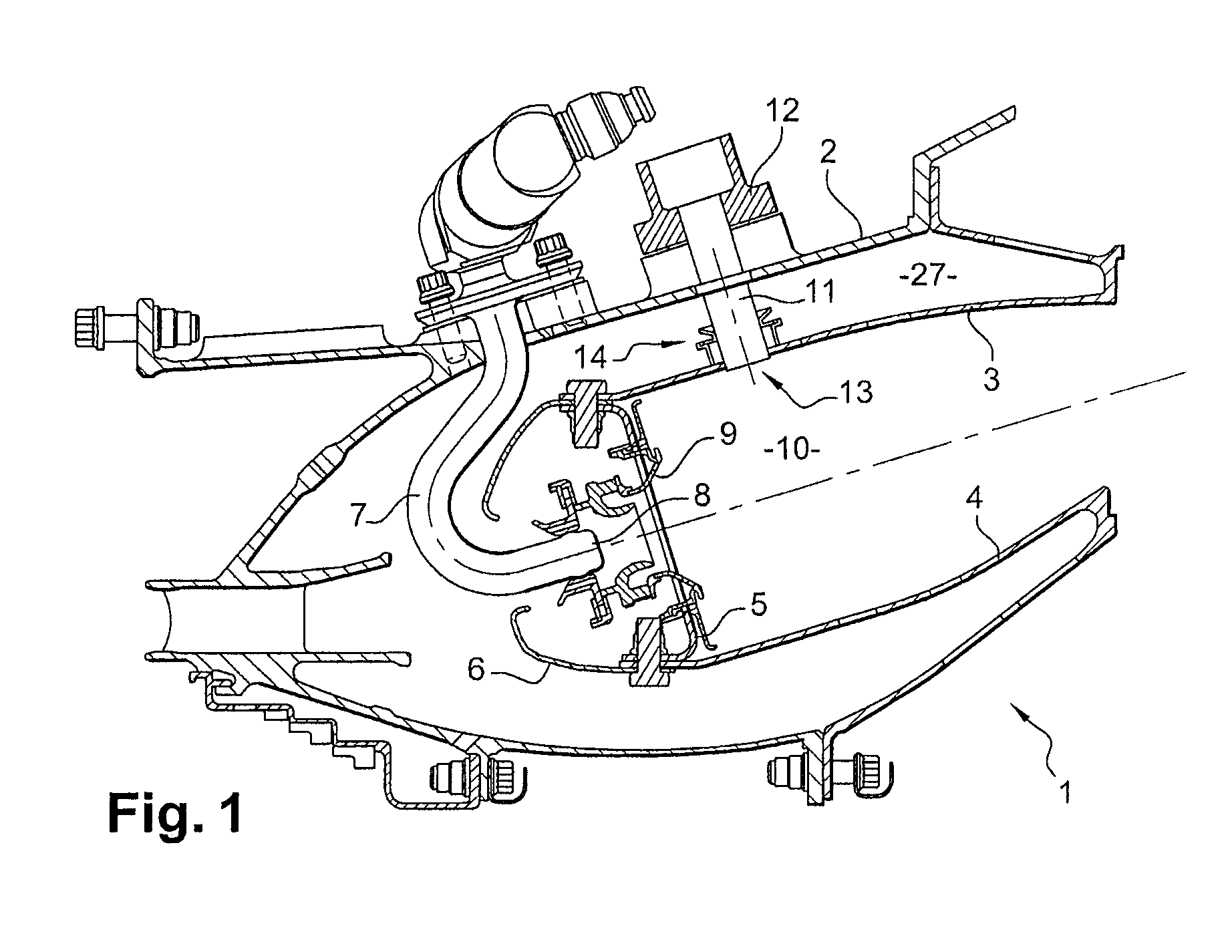
[0033]As shown in FIGS. 1 and 2, an annular combustion chamber 1 of a turbomachine such as an airplane turboprop or turbojet is mounted in an outer casing 2 and includes an outer shroud 3 forming a body of revolution having a downstream annular flange for fastening to the casing 2, an inner shroud 4 forming a body of revolution having a downstream annular flange for mounting to an inner casing, and a chamber end wall 5 having fairings 6 mounted thereon that extend upstream.

[0034]Fuel injector pipes 7 distributed around the axis of the turbomachine open out into the chamber end wall 5 via injector heads 8. Injector systems 9 are disposed around each injector head 8.

[0035]The flow of air delivered by the compressor of the turbomachine is guided by the fairings 6 and shared between a central stream for feeding the combustion chamber 1 and two peripheral streams for flowing around the combustion chamber.

[0036]The injector systems 9 form turbulent incoming air flows in a primary combusti...


PUM


Abstract

The invention relates to a turbomachine combustion chamber including at least one ignition spark plug carried by an outer casing and extending in guide means carried by a wall of the chamber, the wall forming a body of revolution, the guide means comprising a tubular guide having the spark plug passing axially therethrough and mounted with axial and transverse clearance on a chimney fastened to the wall of the chamber and opening out into the chamber. In order to reduce wear of the spark plug in operation, the spark plug is mounted by being fastened in a sheath, the tubular guide being slidably mounted around the sheath.

Description

FIELD OF THE INVENTION[0001]The present invention relates essentially to guiding an ignition spark plug in an annular combustion chamber of a turbomachine such as an airplane turboprop or turbojet.BACKGROUND OF THE INVENTION[0002]An annular combustion chamber of a turbomachine comprises an annular chamber end wall that is connected to two substantially circularly cylindrical shrouds that are coaxial and that extend downstream, together with a fairing or covering fastened on the chamber end wall and extending upstream.[0003]The fairing guides the flow of air delivered by the turbomachine compressor and shares it between a central stream feeding the combustion chamber and two peripheral streams flowing past the combustion chamber.[0004]The air from the compressor is taken into the combustion chamber and mixed with fuel, the mixture being ignited by means of at least one ignition spark plug mounted on an outer casing and passing through an orifice in the outer shroud.[0005]In order to ...

Claims


Application Information

Patent Timeline
Patent Type & Authority Applications(United States)
IPC IPC(8): F02C7/266F02C1/00
CPCF02C7/266F23D2207/00F23R3/06Y02T50/675F23R2900/00005F23R2900/03044F23R3/60Y02T50/60
Inventor LAINS, DOMINIQUE MAURICE JACQUESLEBLOND, NICOLAS CHRISTIAN RAYMONDPIEUSSERGUES, CHRISTOPHE
Owner SN DETUDE & DE CONSTR DE MOTEURS DAVIATION S N E C M A
Why Eureka
Try Eureka