Method for Operating an Exhaust Gas Treatment System Having an SCR Catalytic Converter

Active Publication Date: 2011-05-19
DAIMLER AG
View PDF10 Cites 29 Cited by
  • Summary
  • Abstract
  • Description
  • Claims
  • Application Information

AI Technical Summary

Benefits of technology

[0020]In a further arrangement of the invention, a correction to a target dosing rate by a changeable long term adaption factor is provided for the model dosing rate with the active filling level regulation and/or with an active efficiency control and in a further arrangement of the invention, a correction to an assumed actual filling level is provided by a changeable short term adaption factor by an active filling level regulation for the ammonia filling level value. Thus, the possibility is provided according to the invention to perform a correction acting directly on the model dosing rate, which will become immediately effective on the one hand, but is possibly however maintained over a longer time on the other hand. On the other hand, the possibility is provided to perform a correction of the modeled NH3 filling level acting in the short term. In this manner, disturbing influences occurring in the short term and disturbing influences effective over a longer time, for example gradually progressing ageing or drift effects, can be compensated for.
[0021]In a further arrangement of the invention, nitrogen oxide emission values and/or ammonia emission values of the exhaust gas are continuously determined, and the nitrogen oxide and/or ammonia emission values are evaluated cyclically with regard to fulfilling the presettable short t

Problems solved by technology

Thus, one problem is determining an appropriate feed rate for the reducing agent while avoiding an overdosing from an undesired slip of NH3.
It has, however, been shown that errors caused by, for example, parameter changes add up in the course of time, so that the correspondence between the modeled NH3 filling level of the catalytic converter and the actual value worsens and dosing errors result in the form of an underdosing or overdosing.
The result of this is a reduced cleaning effect or an increased NH3 slip.
The use of a computer model thereby allows for th

Method used


Image

  • Method for Operating an Exhaust Gas Treatment System Having an SCR Catalytic Converter
  • Method for Operating an Exhaust Gas Treatment System Having an SCR Catalytic Converter
  • Method for Operating an Exhaust Gas Treatment System Having an SCR Catalytic Converter

Examples


Example

DETAILED DESCRIPTION OF THE DRAWING FIGURES

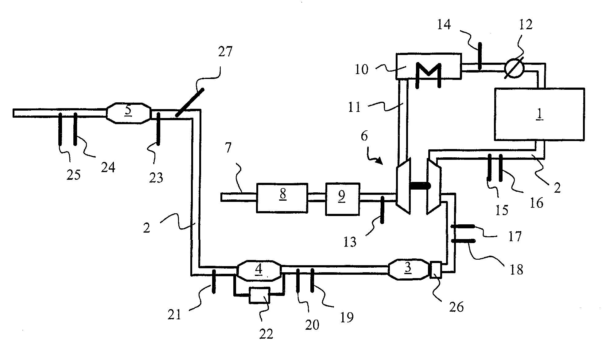
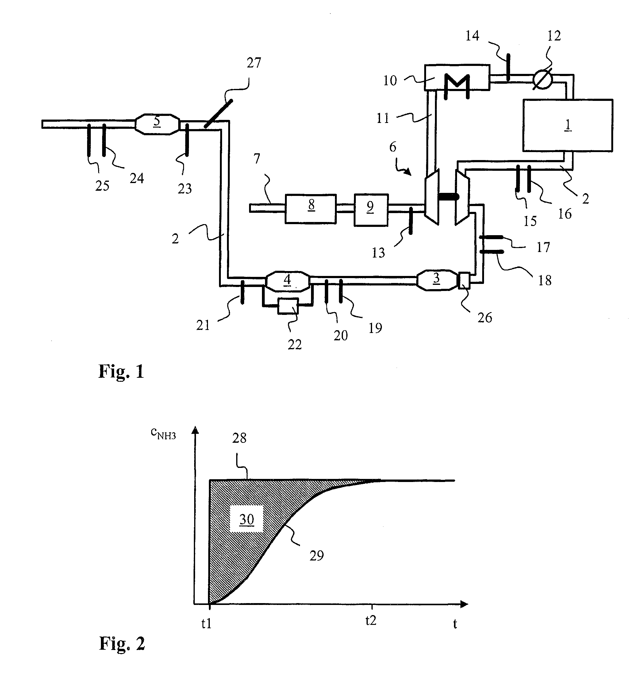
[0033]FIG. 1 shows a schematic block diagram of an internal combustion 1 engine in an exemplary manner of a motor vehicle, not shown with an associated exhaust gas cleaning system. The internal combustion engine 1 is can be an air-compressing internal combustion engine, which will be referred to herein as a diesel engine. The exhaust gas ejected from the diesel engine 1 is received by an exhaust gas line 2 and successively flows through an oxidation catalytic converter 3, a particle filter 4 and a NOx reducing catalytic converter 5. The oxidation catalytic converter 3 and the particle filter 4 can also be arranged in a common housing close to each other. The particle filter 4 is preferably provided with a catalytic coating which promotes a soot combustion and / or a NO oxidation.

[0034]For heating the oxidation catalytic converter 3 or the exhaust gas, a heating device 26 can be arranged in the exhaust gas line 2 on the inlet side of the oxida...


PUM

PropertyMeasurementUnit
Temperatureaaaaaaaaaa
Levelaaaaaaaaaa

Abstract

A method for operating an exhaust gas treatment system that includes an SCR catalytic converter is provided. Either a model-based filling level regulation for achieving the target filling level or a model-based efficiency control for achieving the target efficiency is performed according to presettable values for certain operating variables such as a temperature of the exhaust gas or of the SCR catalytic converter.

Description

CROSS-REFERENCE TO RELATED APPLICATIONS[0001]The present application is a national stage application of PCT International Application No. PCT / EP2009 / 005304, filed Jul. 22, 2009, and claims priority under 35 U.S.C. §119 to German Patent Application No. 10 2008 036 885.7, filed Aug. 7, 2008, the entire disclosures of these documents are herein expressly incorporated by reference.BACKGROUND AND SUMMARY OF THE INVENTION[0002]The present invention relates to a method for operating an exhaust gas treatment system, comprising an SCR catalytic converter for cleaning an exhaust gas of a motor vehicle internal combustion engine, wherein an ammonia-containing reducing agent is dosed to the exhaust gas and an exhaust enriched with NH3 according to the dosing is fed to the SCR catalytic converter, wherein an ammonia filling level value for a filling level of ammonia stored in the SCR catalytic converter is calculated by a computer model.[0003]For the catalytically supported removal of nitrogen o...

Claims


Application Information

Patent Timeline
IPC IPC(8): F01N3/18
CPCB01D53/9409Y02T10/24B01D53/9495B01D2251/2067B01D2255/20723B01D2255/20776B01D2255/50B01D2258/012F01N3/208F01N9/00F01N2560/021F01N2560/026F01N2570/14F01N2900/0404F01N2900/1622Y02T10/47B01D53/9477Y02A50/20Y02T10/12Y02T10/40
Inventor CHRISTNER, BERNDPAULE, MARKUS
Owner DAIMLER AG
Why Eureka
Try Eureka