Flange Bolt Cutter

a technology for flange bolts and cutters, which is applied in the field of flange bolt cutters, can solve the problems of limited life of oil and natural gas platforms and installations, controversial use of explosives, and long time-consuming to decommission, so as to reduce the time it takes to decommission and reduce the cost of abandonmen

Active Publication Date: 2011-05-19
CYPRESS PIPELINE & PROCESS SERVICES LLC
View PDF11 Cites 14 Cited by
  • Summary
  • Abstract
  • Description
  • Claims
  • Application Information

AI Technical Summary

Benefits of technology

[0006]It is an object of the present invention to provide a means for reducing the costs of decommissioning abandoned

Problems solved by technology

Oil and natural gas platforms and installations have a limited life of operations.
However, the use of explosives has become controversial because explosions, particularly underwater explosions, generate intense shock waves that cause instantaneous lethal impacts for marine life residing on or near the platform structure.
One of the problems encountered while using non-explosive methods to remove vertical pipes during decommissioning is that the vertical pipes usually have been exposed to the marine elements for several years, if not

Method used


Image

  • Flange Bolt Cutter
  • Flange Bolt Cutter
  • Flange Bolt Cutter

Examples


Embodiment Construction

[0025]While the present invention will be described with reference to preferred embodiments, it will be understood by those skilled in the art that various changes may be made and equivalents may be substituted for elements thereof without departing from the scope of the invention. In addition, many modifications may be made to adapt a particular situation or material to the teachings of the invention without departing from the essential scope thereof. Therefore, it is intended that the present invention not be limited to the particular embodiments disclosed as the best mode contemplated for carrying out this invention.

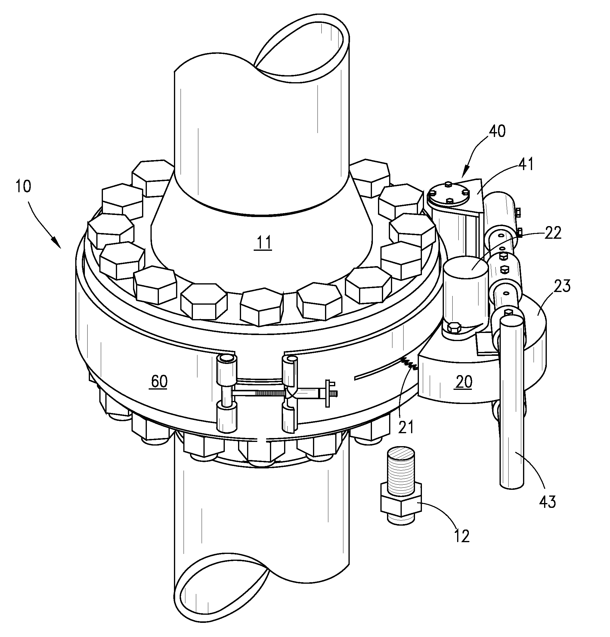
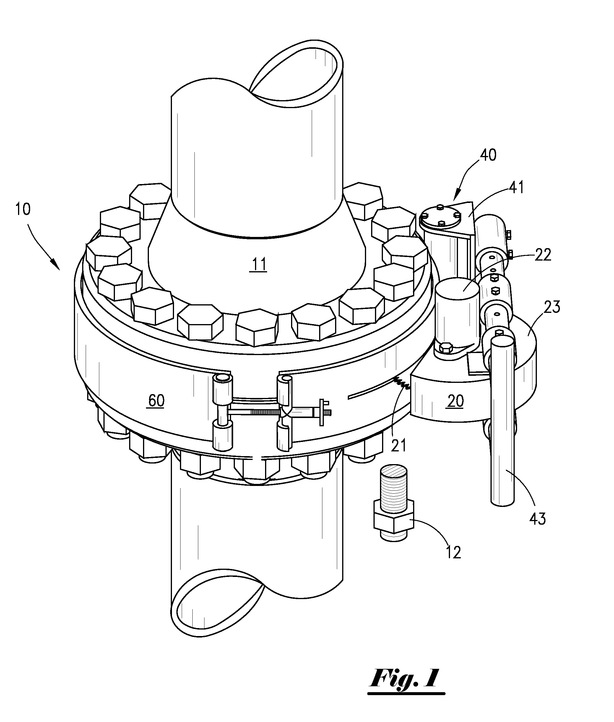
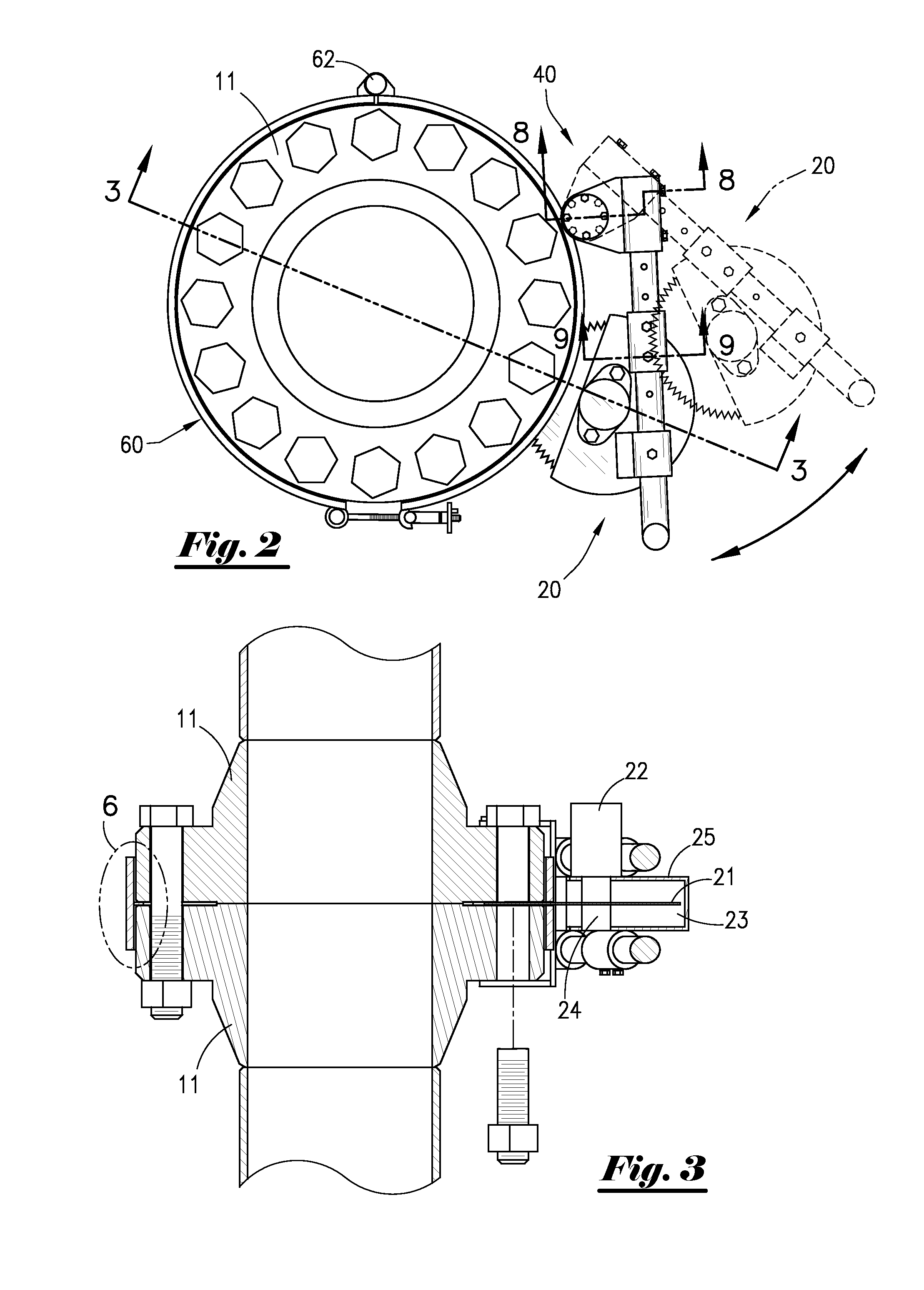
[0026]FIG. 1 shows flange bolt cutter 10 operatively engaged about two flanges 11 that are secured together by flange bolts 12. Flange bolt cutter 10 includes a saw assembly 20, a pivot assembly 40, and a flange band assembly 60. Saw assembly 20 includes a circular saw blade 21, a motor 22 for rotatably driving said circular saw blade 21, and a blade case 23 for subst...


PUM


Abstract

A flange bolt cutter for separating two connected flanges. The flange bolt cutter contains a circular saw blade pivotally connected to an adjustable flange band. The flange band contains an alignment ring for aligning the circular saw blade about the midpoint between two connected flanges. The flange bolt cutter is hydraulically operated. The adjustable flange band may be formed in two band sections hinged together and containing a rotatable bolt and handle for tightening and loosening the band sections around the flange connection.

Description

CROSS-REFERENCE TO RELATED APPLICATIONS[0001]This application claims priority to Provisional Patent Application No. 61 / 249,243, filed on 6 Oct. 2009, which is incorporated herein by reference.FIELD OF THE INVENTION[0002]The present invention relates generally to an apparatus for cutting bolts, and more particularly, an apparatus for cutting flange bolts.BACKGROUND OF THE INVENTION[0003]Oil and natural gas platforms and installations have a limited life of operations. When oil runs out, the platforms and installations are decommissioned using a number of different alternatives. As examples, the platforms and installations may be (a) left completely or partially in the water (often called “reefing”); (b) removed and then reused in another location; or (c) hauled to shore for scrapping or recycling.[0004]The majority of platform decommissioning in the world has occurred in the Gulf of Mexico. The process of decommissioning typically begins with well abandonment in which the well bores ...

Claims


Application Information

Patent Timeline
IPC IPC(8): B23D47/00
CPCB23D45/12Y10T83/68Y10T83/667
Inventor ELLIS, SHAWNSNYDER, BENJAMIN J.RICHARD, RUSTY
Owner CYPRESS PIPELINE & PROCESS SERVICES LLC
Why Eureka
Try Eureka