Device for applying adhesive

Inactive Publication Date: 2011-05-19
SIKA TECH AG
View PDF7 Cites 18 Cited by
  • Summary
  • Abstract
  • Description
  • Claims
  • Application Information

AI Technical Summary

Benefits of technology

[0005]The object of this invention is therefore to provide a device that simply and easily enables an adhesive to be applied to and distributed over a planar substrate, and allows the quantity of waste and / or any health hazards created during the application to be reduced.

Problems solved by technology

The disadvantageous aspect in using this type of distribution device for applying the adhesive, however, is that the adhesive is frequently applied inhomogeneously due to the fact that individual isolated beads are present on the surface, and this results in a defective adhesive bond after joining is effected.
This occurs particularly in situations involving porous or elastic substrates that are difficult to press together.
However, due to the viscosity of the adhesive and the nozzle geometry, it is very difficult to ensure that the flow of adhesive exiting the wide-slit nozzle is homogeneous across the entire width and is distributed uniformly over the surface to be bonded.
Whenever planar substrates are bonded over their entire surface or over their full area, the wide-slit nozzle must also project beyond the edge, thereby necessarily resulting in an increase in material consumption and waste.
However, these spray nozzles at times are, first of all, of very complex design and / or also extremely susceptible to types of contamination, and as a result are very labor-intensive in terms of maintenance and cleaning.
Additionally, it is difficult to restrict the location of the adhesive when using this method due to the spray mist that is generated.
Material is thus applied to locations where it is not at all required, or even desirable, and this situation results in an increase in the consumption of material, or an increase in the cost of removing waste.
In addition, the presence of the spray mist results in extensive contamination and entails significant health risks—especially if the adhesive contains reactive substances, in particular, those that are hazardous to health.
All of the above generates significant and undesirable added costs.

Method used


Image

  • Device for applying adhesive
  • Device for applying adhesive
  • Device for applying adhesive

Examples


Embodiment Construction

[0005]The object of this invention is therefore to provide a device that simply and easily enables an adhesive to be applied to and distributed over a planar substrate, and allows the quantity of waste and / or any health hazards created during the application to be reduced.

[0006]Surprisingly, it is found that a device as set forth in Claim 1 and / or a method as set forth in Claim 11 can achieve this object.

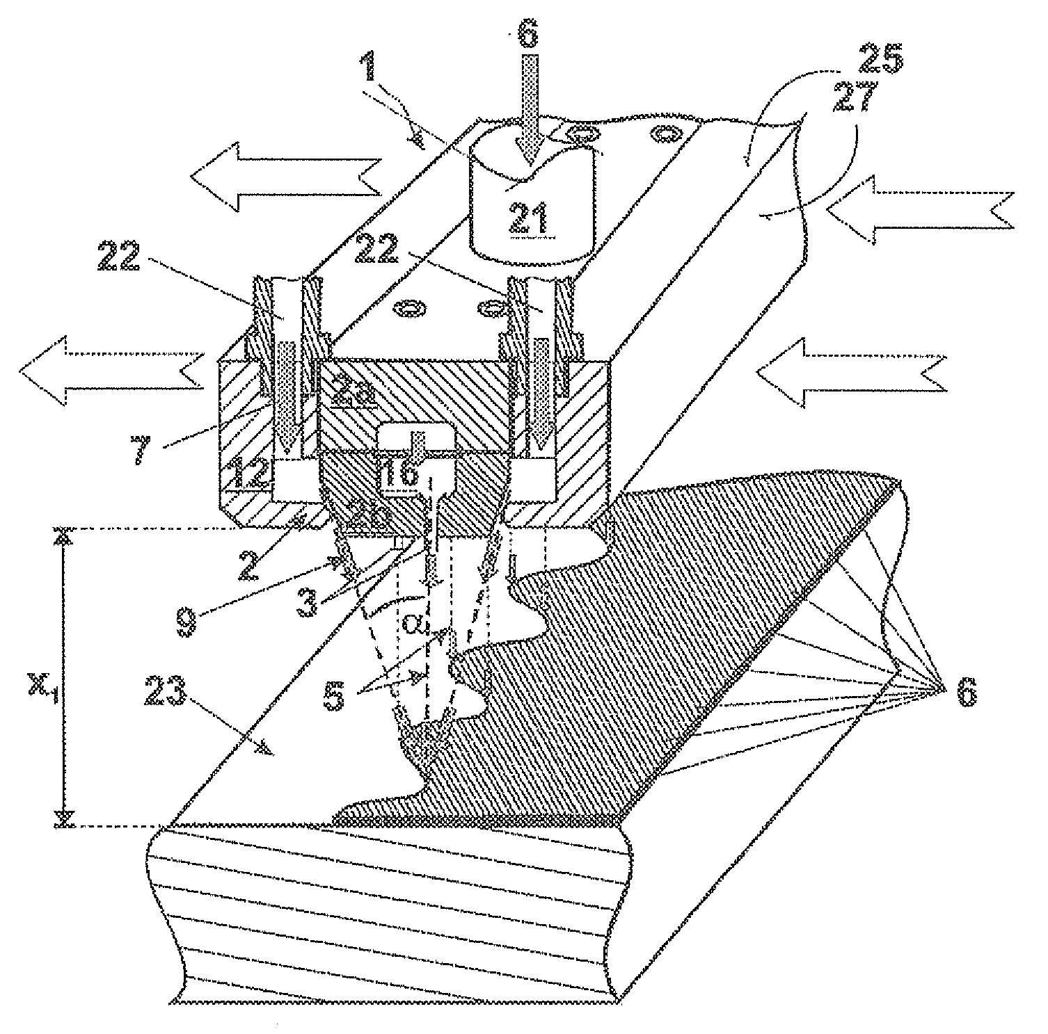
[0007]The invention enables the adhesive to be applied quickly over a large area of a planar substrate. Fundamental advantages are created by a simple, inexpensively-implemented constructive design for the device, and these allow expensive ancillary equipment either to be eliminated or at least significantly reduced in scope. Due to the advantageous manner of application, the invention succeeds in avoiding material wastage, while also achieving to the greatest extent possible a full-coverage, homogenous distribution of the adhesive.

[0008]It has been found that the device can be used...


PUM

PropertyMeasurementUnit
Angleaaaaaaaaaa
Angleaaaaaaaaaa
Adhesivityaaaaaaaaaa

Abstract

A device for applying adhesive having both an adhesive distribution housing comprising a plurality of adhesive discharge nozzles and at least one gas discharge nozzle disposed in the longitudinal axis of the adhesive distribution housing. Fundamental advantages are created by a simple, inexpensively-implemented constructive design for the device, thereby enabling expensive ancillary equipment either to be eliminated or at least significantly reduced in scope. Due to the advantageous manner of application, the invention succeeds in avoiding material wastage, while also achieving to the greatest extent possible a full-coverage, homogenous distribution of the adhesive.

Description

TECHNICAL FIELD[0001]The invention relates to the field of devices for applying adhesives.PRIOR ART[0002]An extremely wide variety of devices is available for applying and distributing adhesives on planar substrates.[0003]In terms of large areas, adhesives are often applied to planar substrates to be bonded using devices that have a plurality of nozzles to discharge the adhesive. The adhesive exits through spaced nozzles from the distribution device and is applied in the form of individual beads on the substrate by moving the device parallel to the surface. For example, WO 99 / 65612 A1 discloses such an adhesive-applying device. The disadvantageous aspect in using this type of distribution device for applying the adhesive, however, is that the adhesive is frequently applied inhomogeneously due to the fact that individual isolated beads are present on the surface, and this results in a defective adhesive bond after joining is effected. This occurs particularly in situations involving ...

Claims


Application Information

Patent Timeline
IPC IPC(8): B32B37/12B05B1/34B05D5/10B05D1/00B05C11/00
CPCB05B7/0815B05C5/027B05B7/0884B05B7/083
Inventor PETERSEN, LARSTHORNBERG, STEN
Owner SIKA TECH AG
Why Eureka
Try Eureka