Fitting torque arm restraint

a technology of arm restraint and fitting, which is applied in the field of mechanical restraints, can solve the problems of destroying the usefulness of the tank, causing significant stress on the portion of the tank adjacent to the outlet, and affecting the use of the tank

Active Publication Date: 2011-05-19
TANK HLDG CORP
View PDF9 Cites 6 Cited by
  • Summary
  • Abstract
  • Description
  • Claims
  • Application Information

AI Technical Summary

Benefits of technology

[0007]This objective has largely been met by the fitting torque arm restraint of the present invention. That is to say, the present invention provides an economical solution to the problem of stress concentrations in the vicinity of fittings of various types, including fluid outlets, by providing a device which is incorporated into a fitting or can be mounted to an existing fitting of a tank to counteract the torque placed on the fitting and adjacent areas of the tank wall.
[0008]Because typical tank side walls are upright where fluid outlets are located on the side wall, they have much more strength in the vertical direction than in the horizontal. Thus, the downward vector force is typically in compression along the upright length of the wall, which is sufficient to support the weight of the tank, the outlet fitting, and any extension. The present invention can be mounted in proximity to horizontal, or inclined walls as well as vertical walls of a tank, and serves to distribute and offset much of the torque applied to the fitting by an outwardly extending arm which attaches to or is provided as a part of the fitting on the inside of the fitting and configured and positioned to press against the tank wall under conditions of excessive torque.
[0010]As a result, a lightweight and inexpensive solution to the problem of torque application to the a fitting such as an outlet fitting and surrounding areas of the tank is provided by the present invention. These and other advantages will be readily appreciated by those skilled in the art with reference to the attached drawings and following description.

Problems solved by technology

These attachments to the fitting can become especially heavy, especially when filled with liquid.
However, such measures are often overlooked or removed, resulting in a cantilever support from the outlet fitting.
Moreover, even when such support is provided, the length of a pipe and its fluid contents in a long length of pipe may still impart a significant stress on the portion of the tank adjacent the outlet.
This stress can cause deformation, such as warping of the tank wall which results in leaks, or even worse, stress fractures which can destroy the usefulness of the tank.

Method used


Image

  • Fitting torque arm restraint
  • Fitting torque arm restraint
  • Fitting torque arm restraint

Examples


first embodiment

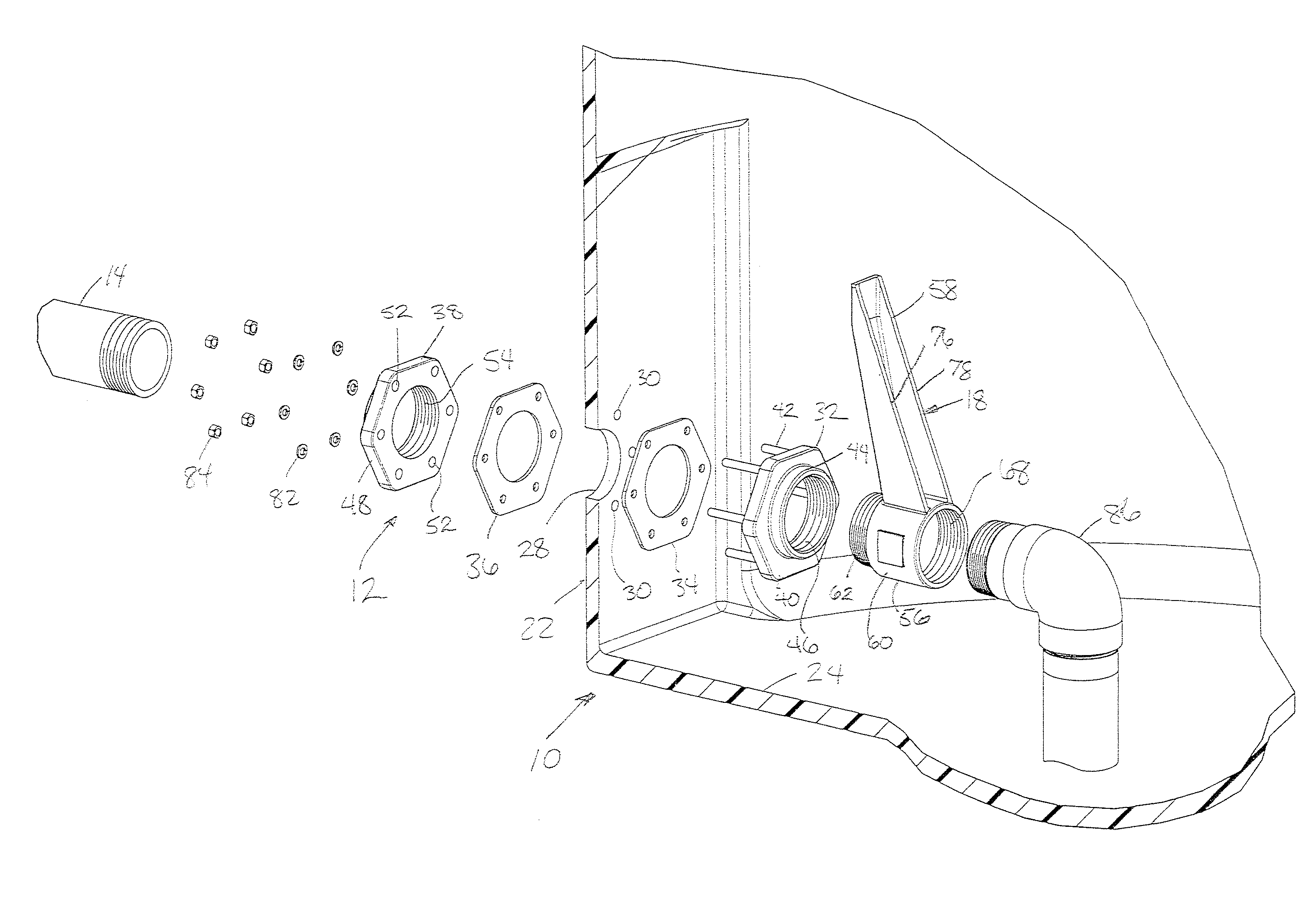
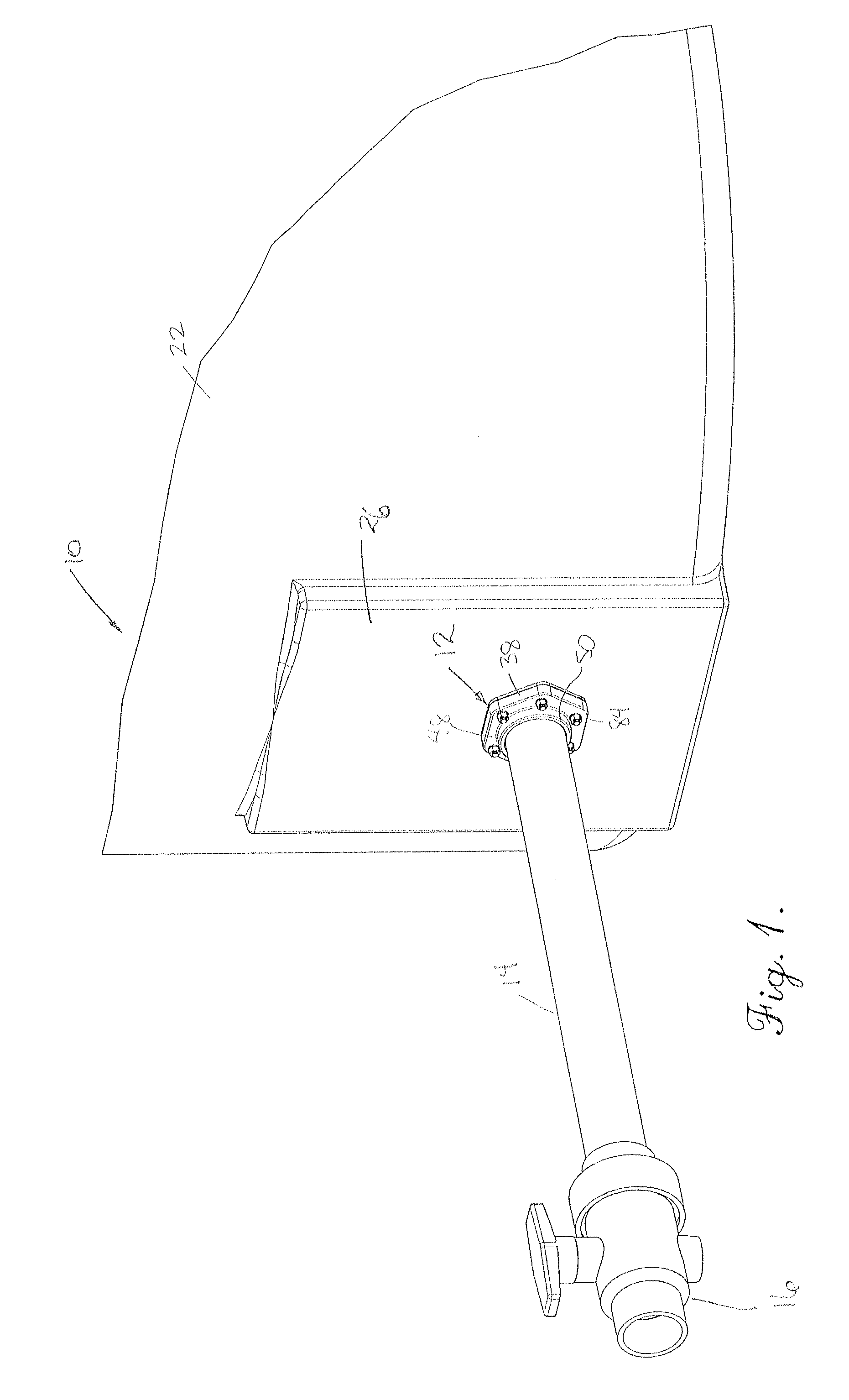
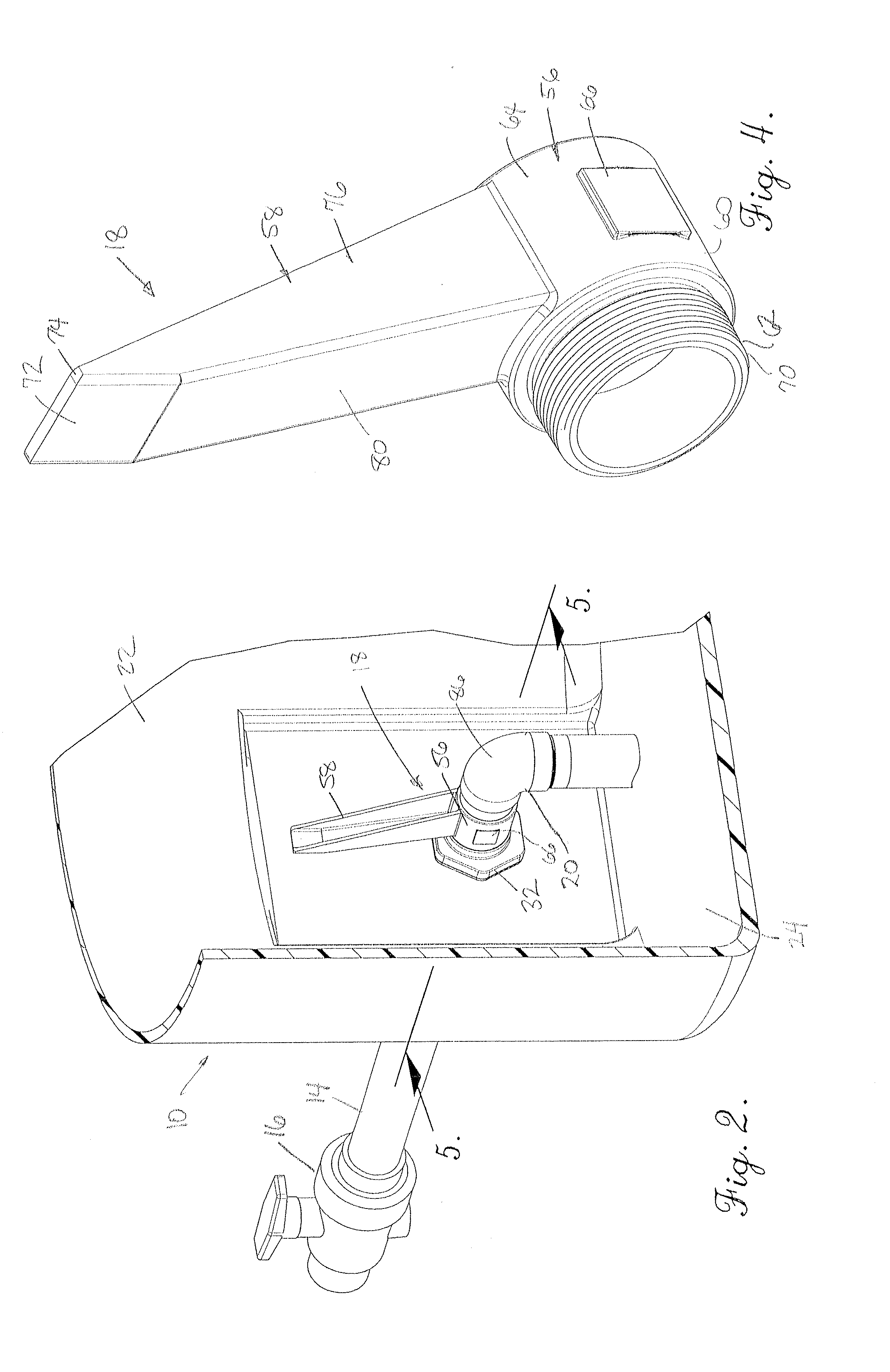
[0018]Referring now to the drawings, a fluid storage tank 10 is provided with a fitting 12 as shown in FIGS. 1 and 2. While the preferred embodiment is shown as used in conjunction with a fitting used as an outlet fitting 12, it is to be appreciated that the present invention is not limited to use on outlet fittings but can be employed for use in conjunction with inlet, instrumentation and other types of fittings as well. As further illustrated in FIG. 1, the outlet fitting 12 is shown connected to an elongated pipe 14 to which a controllable valve 16 is connected. FIG. 2 shows the interior of the tank 10, with a torque arm restraint 18 configured for mounting to an existing outlet fitting 12. An outflow pipe 20, used to collect liquid held within the tank 10 and deliver the collected liquid to the outlet fitting 12, is mounted to the torque arm restraint 18.

[0019]In greater detail, the tank 10 includes a surrounding side wall 22 and a bottom wall 24, which are preferably molded as ...

second embodiment

[0022]the torque arm restraint 100 is shown in FIGS. 6 and 7, wherein like numbers are used to identify like elements of the embodiment shown in FIGS. 1-5. In this embodiment, the torque arm restraint 100 includes a body 102 and an arm 104 unitary and integral with the body 102 and extending transversely from central axis A of the tubular body 102. The body 102 is provided as an integral and unitary part of an inside flange 106 of the fitting 108. The fitting 108 includes an outside flange 38 and gaskets 34 and 36 as described above, and the inside flange 106 includes a bore 46 as described above. The inside flange 106 includes bolts 42 as described above for insertion in the complementally configured and arranged holes 52 of the outside flange 38, to which it is secured by nuts 84. The body 102 includes a coupler 110 having an internally threaded inner surface 68 adapted to mount an outflow pipe 20 or the like.

[0023]The arm 104 of the torque arm restraint 100 extends transversely t...


PUM

PropertyMeasurementUnit
angleaaaaaaaaaa
angleaaaaaaaaaa
angleaaaaaaaaaa

Abstract

A torque arm restraint is provided with a body having a bore including an axis and an arm extending from said body transversely to the axis. The restraint is adapted for resisting torque applied to the fitting of a liquid storage tank, and is configured either for mounting on a fitting or as a component of the fitting. The fitting may be an outlet fitting having a pipe mounted thereto and extending from the wall of the tank. The tubular body permits passage of instrumentation or liquid through the torque arm restraint and the fitting and the arm is provided with an abutment surface positioned proximate to the inside surface of the tank wall, either in engagement or in spaced relationship, whereby the arm resists torque applied to the fitting from outside of the tank. The body may include an attachment member which extends axially from the body and adapted, for example by threads, for mounting to a tank fitting, and the body may be coupled to a pipe within the interior of the tank.

Description

BACKGROUND OF THE INVENTION[0001]1. Field of the Invention[0002]The present invention is concerned with a mechanical restraint to resist the influence of torque applied to fittings, particularly fittings of vessels such as fluid containment tanks. More particularly, it is directed to a fitting including a restraint and a restraint which can be mounted to a fitting and positioned interiorly of a fluid tank in order to avoid damage to the sealing integrity between the outlet assembly and the tank.[0003]2. Description of the Prior Art[0004]Vessels for holding liquids are used in a variety of industries and while they may be configured differently and constructed of various materials. A variety of different fittings for various purposes such as inlet, instrumentation and the like are provided on a tank. Fittings which are used as part of a discharge outlet may be of particular interest as they are often constructed to use gravity so as to discharge the liquid contents of the tank throug...

Claims


Application Information

Patent Timeline
Patent Type & Authority Applications(United States)
IPC IPC(8): B65D1/46B65D25/00B23P11/00
CPCY10T29/49826F16L5/08
Inventor OLTMAN, DARRELL A.
Owner TANK HLDG CORP
Why Eureka
Try Eureka