Cross-member for a rear twist-beam axle suspension for a motor-vehicle and method for its production

a technology of twist-beam axle and cross-member, which is applied in the direction of resilient suspensions, interconnection systems, metal-working apparatus, etc., can solve the problems of not being able to achieve cross-members are not suitable for applications requiring high torsional stiffness, and the section does not allow for achieving particularly high values of torsional stiffness, etc., to achieve greater torsion moment, increase the mechanical strength, and increase the torsional sti

Inactive Publication Date: 2011-05-19
SISTEMI SOSPENSIONI SPA
View PDF16 Cites 39 Cited by
  • Summary
  • Abstract
  • Description
  • Claims
  • Application Information

AI Technical Summary

Benefits of technology

[0016]By virtue of the arched middle portion, the cross-member can be used in rear twist-beam axle suspensions for four- or rear-wheel drive motor vehicles without interfering with the drive shaft. At the same time, by virtue of the horizontal straight end portions the cross-member on the one hand has less problems of space availability than the prior art discussed above and on the other hand has joining edges with the trailing arms which have a more regular shape than the prior art discussed above, whereby the above-mentioned problems due to the generation of stress peaks do not occur. Moreover, by virtue of the use of a squashed tube a middle cross-section is obtained which on the one hand is closed, and is therefore able to provide high values of torsional stiffness even without a torsion bar (which could not even be used due to the bowed shape of the cross-member), and on the other hand can be suitably shaped to locate the shear centre in the desired position in view of the kinematic and elasto-kinematic requirements of the suspension.
[0018]According to another feature of the invention, the end portions of the cross-member intended to be securely connected to the trailing arms of the twist-beam axle have an enlarged cross-section, that is to say, a cross-section of larger perimeter than that of the cross-section of the middle portion of the cross-member. The amount of the increase in the perimeter of the end portions with respect to the middle portion varies depending on the specific application, naturally within the limits linked to the ability of the material of the cross-member to absorb the deformation. The resulting increase in the inertial characteristics of the joining area with the trailing arms leads to an increase in the mechanical strength and hence to the possibility to transmit a greater torsion moment, as well as to an increase in the stiffness of the twist-beam axle under lateral loads, and hence to an improvement of the handling performances of the vehicle.

Problems solved by technology

Such a conformation of the cross-member causes problems of space availability when the wheels carried by the trailing arms of the twist-beam axle are driving wheels.
The problems of space availability are basically due to the presence of the drive shaft which extends longitudinally, i.e., perpendicularly to the cross-member, thereby “crossing” the cross-member itself.
Since the trailing arms extend on the other hand horizontally, the welded joints between the ends of the cross-member and the trailing arms have therefore a rather irregular and complex shape which leads to an irregular stress distribution with peak values which may cause structural problems.
The choice of an open section does not allow to achieve particularly high values of torsional stiffness and makes therefore the cross-member not suitable for those application requiring a high torsional stiffness.
Furthermore, the arched shape of the cross-member does not allow to add a torsion bar to increase the torsional stiffness of the cross-member.

Method used


Image

  • Cross-member for a rear twist-beam axle suspension for a motor-vehicle and method for its production
  • Cross-member for a rear twist-beam axle suspension for a motor-vehicle and method for its production
  • Cross-member for a rear twist-beam axle suspension for a motor-vehicle and method for its production

Examples


Embodiment Construction

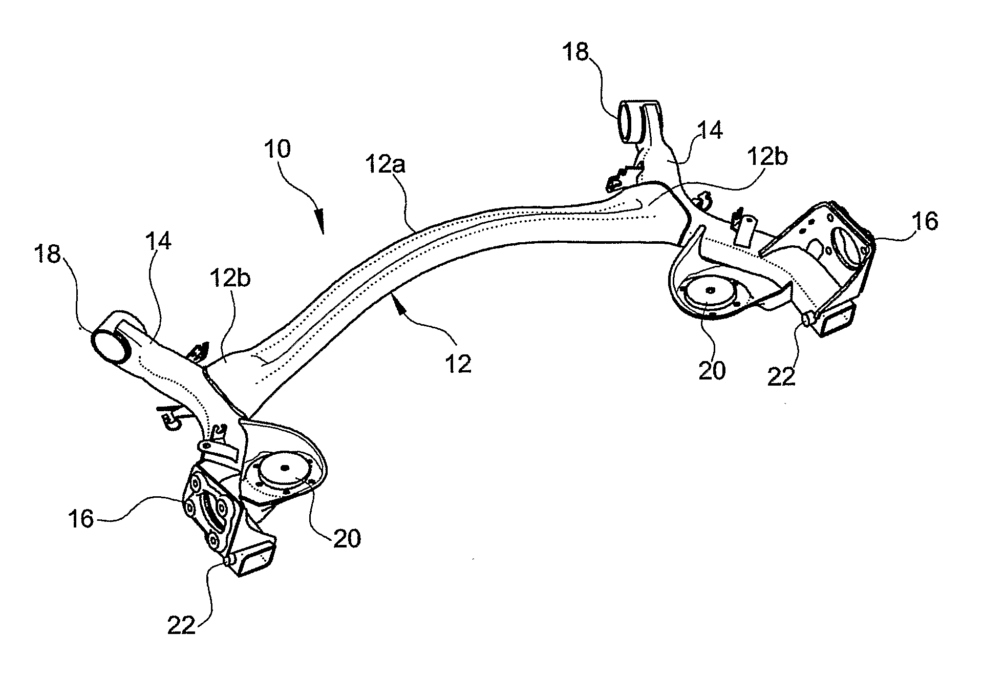
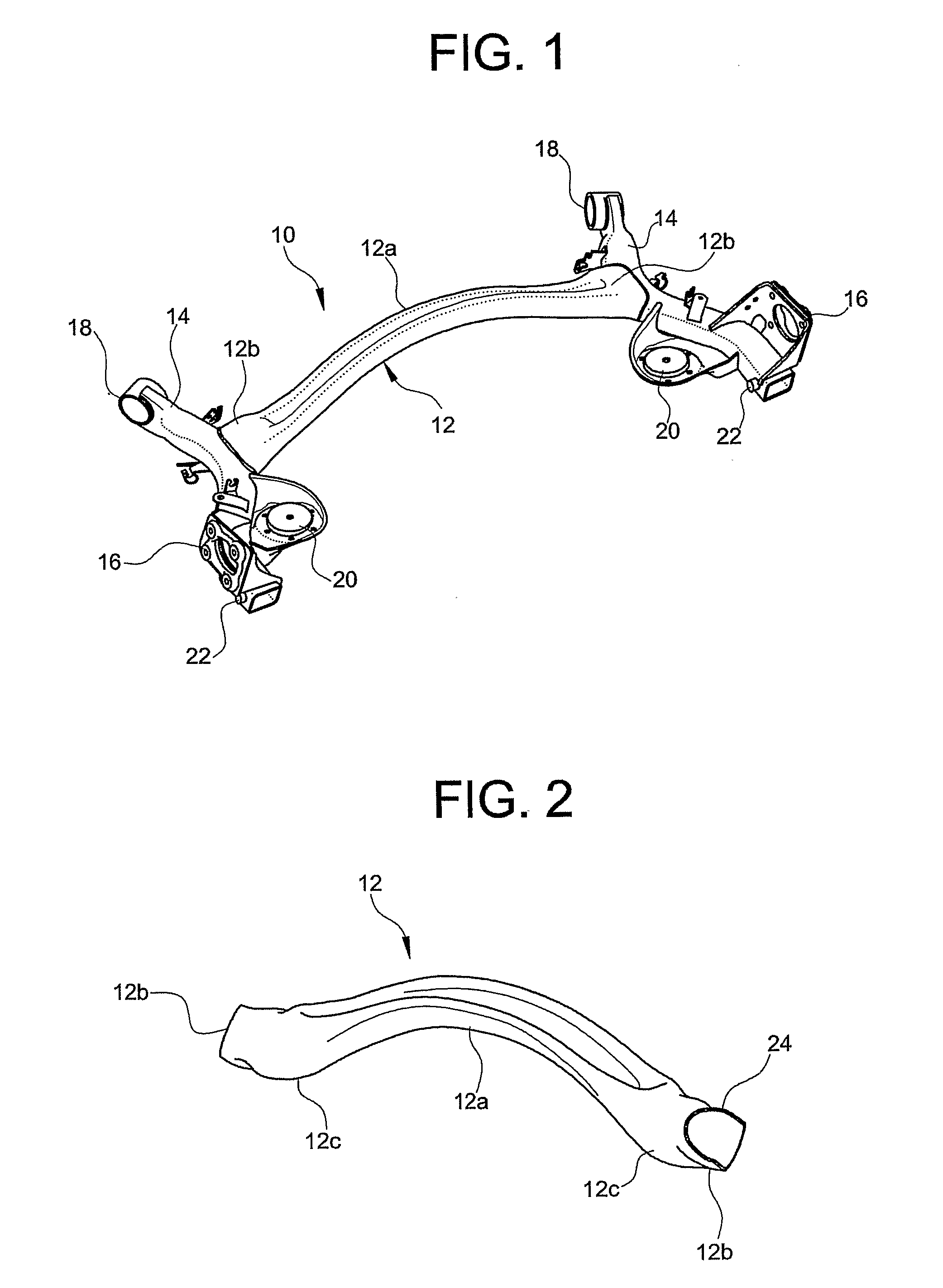
[0025]With reference first to FIG. 1, a twist-beam axle for a motor-vehicle suspension, particularly for a rear suspension, is generally indicated 10 and basically comprises a bowed cross-member 12 and a pair of trailing arms 14 securely connected each to a respective side end of the cross-member 12. The trailing arms 14 carry respective wheel-carrying members 16, respective bushing seats 18 for articulated connection of the twist-beam axle 10 to the vehicle body (not shown), respective plates 20 for support of the springs (not shown), as well as respective attachment members 22 for the shock-absorbers (also not shown).

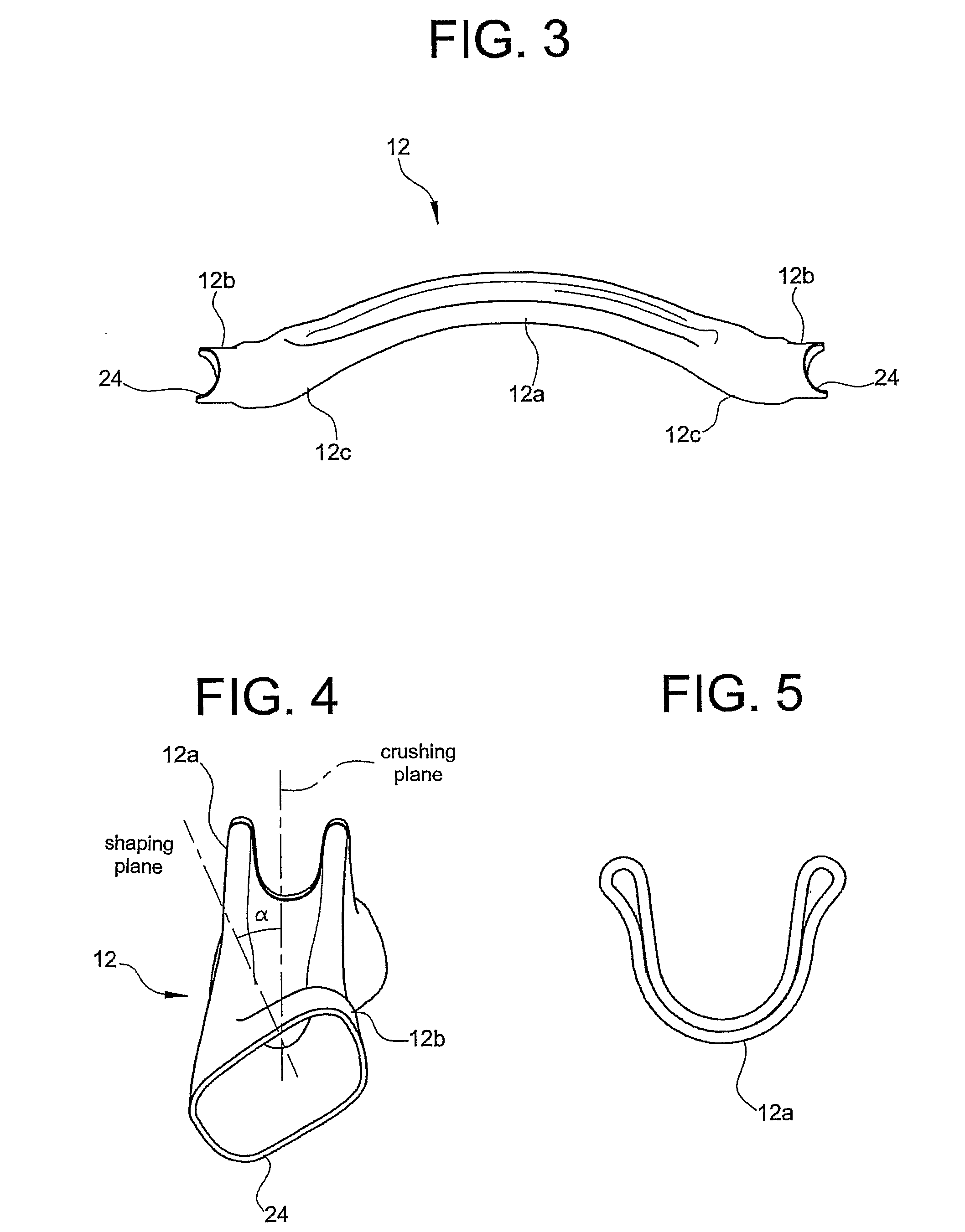
[0026]The cross-member 12 includes a single tube of steel, such as manganese-boron steel (for instance, the 20MnB5 steel), or alternatively of low-alloy high-strength steel (cold- or hot-rolled), of multi-phase high-strength steel (cold- or hot-rolled), of two-phase high-strength steel (for instance, the DP600 steel), of ferritic-bainitic high-strength steel or again ...


PUM

PropertyMeasurementUnit
vertical distanceaaaaaaaaaa
perimeteraaaaaaaaaa
lengthaaaaaaaaaa

Abstract

A cross-member for a motor-vehicle twist-beam axle suspension includes a single piece of steel that defines a closed cross-section and integrally forms a middle section, a pair of end sections, and a pair of joining sections. The middle section has a center axis extending along a curvilinear path lying in a first plane and a squashed portion extending in a second plane inclined to the first plane. The end sections are adapted to be securely connected to respective trailing arms of the twist-beam axle suspension. Each of the joining sections is interposed between the middle section and the respective end section and defines an opposite concavity with respect to the middle section. A twist-beam axle suspension for a motor vehicle includes the cross-member and a pair of trailing arms. A method produces the cross-member for a motor-vehicle twist-beam axle suspension.

Description

CROSS-REFERENCE TO RELATED APPLICATIONS[0001]This application claims priority to and benefit of the filing date of PCT Patent Application PCT / IB2008 / 055103 entitled “CROSS-MEMBER FOR A REAR TWIST-BEAM AXLE SUSPENSION FOR A MOTOR VEHICLE AND METHOD FOR ITS PRODUCTION” and filed on Dec. 4, 2008, which claims priority to and benefit of the filing date of Italian Patent Application TO2008A000521 filed on Jul. 8, 2008.BACKGROUND OF INVENTION[0002]1. Field of Invention[0003]The present invention relates to a cross-member for a twist-beam axle suspension for a motor vehicle, particularly for a rear suspension, as well as to method for its production.[0004]2. Description of Related Art[0005]Rear twist-beam axle suspensions for motor vehicles are known which comprise a central cross-member and a pair of trailing arms which are rigidly connected to the opposite transverse ends of the cross-member and carry at their rear ends respective members for support of the wheel axles and at their front...

Claims


Application Information

Patent Timeline
Patent Type & Authority Applications(United States)
IPC IPC(8): B60G21/055B21D53/88
CPCB60G21/051B60G2200/21B60G2206/012Y10T29/49622B60G2206/72B60G2206/8102B60G2206/8107B60G2206/202
Inventor ALESSO, GUIDO SEBASTIANOTRINCHERA, MASSIMOCASTAGNO, LORENZOSANTINI, ANDREAMONCHIERO, PIERO
Owner SISTEMI SOSPENSIONI SPA
Why Eureka
Try Eureka