Mounting structure of front body frame in vehicle

a technology for mounting structures and vehicles, which is applied in vehicle maintenance, vehicle cleaning, transportation and packaging, etc., can solve the problems of reducing the stability of adjusting the vehicle, the components constituting the circumference of the engine compartment are not firmly combined with each other, etc., and achieve the effect of ensuring the rigidity of the circumference of the engine compartment and ensuring the stability

Active Publication Date: 2011-05-19
HYUNDAI MOTOR CO LTD +1
View PDF3 Cites 18 Cited by
  • Summary
  • Abstract
  • Description
  • Claims
  • Application Information

AI Technical Summary

Benefits of technology

[0014]According to the mounting structure of the front body panel in the vehicle of the present invention, it may secure the rigidity of the body shell and the chassis around the engine compartment, and may also secure the stability for adjusting the vehicle with regard to an external force which may occur while the vehicle is in motion,

Problems solved by technology

But, in case of the above-described mounting structure of the front body frame in the vehicle of the prior art, components constituting for the circumference of the engine compartment are not firmly combined with each ot

Method used


Image

  • Mounting structure of front body frame in vehicle
  • Mounting structure of front body frame in vehicle
  • Mounting structure of front body frame in vehicle

Examples


Embodiment Construction

[0020]Reference will now be made in detail to various embodiments of the present invention(s), examples of which are illustrated in the accompanying drawings and described below. While the invention(s) will be described in conjunction with exemplary embodiments, it will be understood that present description is not intended to limit the invention(s) to those exemplary embodiments. On the contrary, the invention(s) is / are intended to cover not only the exemplary embodiments, but also various alternatives, modifications, equivalents and other embodiments, which may be included within the spirit and scope of the invention as defined by the appended claims.

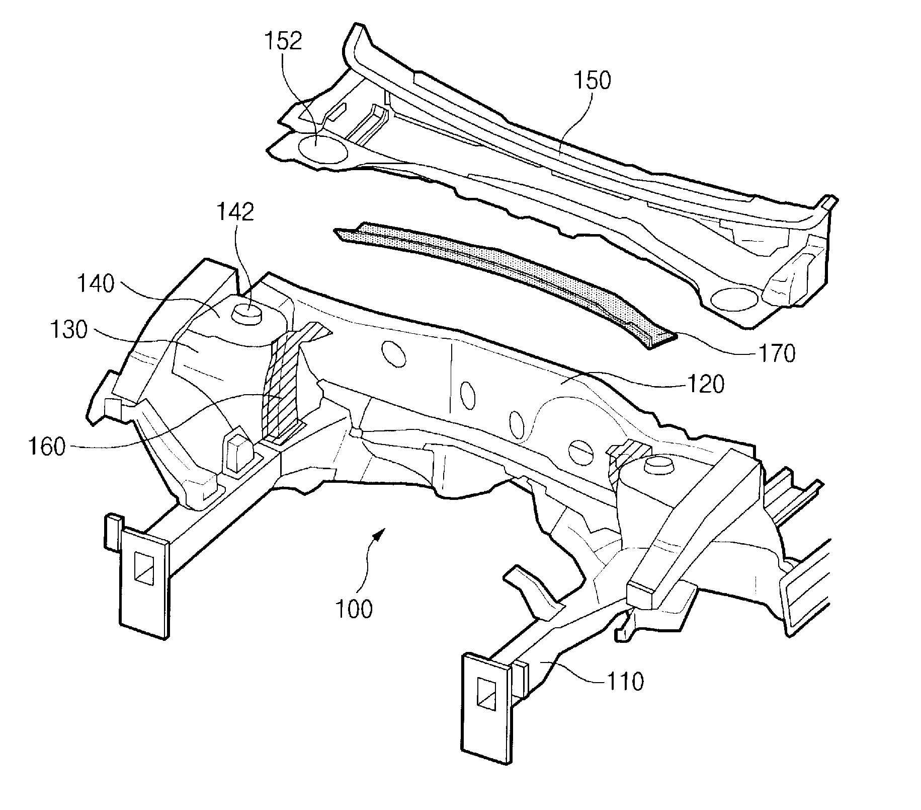
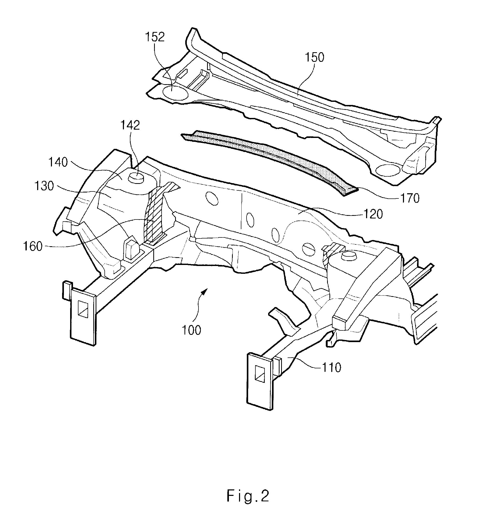
[0021]Now, a mounting structure between a body shell and a chassis around an engine compartment according to various embodiments of the present invention will be explained in more detail with reference to the attached drawings.

[0022]FIG. 2 is a perspective view for illustrating a mounting structure between a body shell and a chassis a...


PUM

PropertyMeasurementUnit
Stiffnessaaaaaaaaaa
Stabilityaaaaaaaaaa

Abstract

A mounting structure of a front body frame in a vehicle, wherein, by improving the mounting structure between a body shell and a chassis around an engine compartment in the vehicle, it may secure the stability of the vehicle as well as the rigidity of the vehicle. As a mounting structure of a front body frame in a vehicle, in which a circumference of an engine compartment includes side members arranged at both lower parts of an engine compartment, a dash panel arranged fin order to form a boundary between the engine compartment and a vehicle compartment, a tire apron arranged at an upper side of both side members, a shock absorber cover arranged on the tire apron, and a cowl panel arranged at an upper side of the dash panel, the mounting structure may include: a pair of support members whose lower part is equipped to be fixed on both side members and whose upper part is equipped to be fixed on the dash panel; a cowl member whose each of two edges are connected to an upper side of the pair of support members by welding, the cowl member arranged to support a lower side of the cowl panel; a pair of side frames arranged at the lower side of the side members along an extension line where the lower part of the support members is extended; and a cross member arranged so that each of the lower parts of the side frames are mutually connected, wherein each of the cowl member, the support members, the side frames and the cross member are connected to be a ring shape.

Description

CROSS-REFERENCE TO RELATED APPLICATION[0001]The present application claims priority to Korean Patent Application Number 10-2009-0111768, filed on Nov. 19, 2009, the entire contents of which are incorporated herein for all purposes by this reference.BACKGROUND OF THE INVENTION[0002]1. Field of the Invention[0003]The present invention relates to a mounting structure of a front body frame in a vehicle. More particularly, the present invention relates to a mounting structure of a front body frame of a vehicle, in which, by improving the mounting structure between a body shell and a chassis around an engine compartment in the vehicle, it may secure the stability of the vehicle as well as the rigidity of the vehicle.[0004]2. Description of Prior Art[0005]In general, a vehicle is structurally divided into a body shell and a chassis. The body shell is a part for forming the appearance of the vehicle by including an engine compartment. The chassis is a part exclusive of the body shell, in wh...

Claims


Application Information

Patent Timeline
IPC IPC(8): B62D25/08B21D53/88
CPCB62D25/081Y10T29/49622B62D25/088B62D25/082B62D21/00B62D25/08
Inventor KIM, YONG KEW
Owner HYUNDAI MOTOR CO LTD
Why Eureka
Try Eureka