Mild hybrid system and method for controlling the same

a hybrid system and hybrid technology, applied in the direction of engine-driven generators, vehicle sub-unit features, electric devices, etc., can solve the problems of reduced fuel efficiency, increased system cost and inefficiency, limited electrical energy recovered during regenerative braking,

Active Publication Date: 2011-05-19
HYUNDAI MOTOR CO LTD
View PDF2 Cites 54 Cited by
  • Summary
  • Abstract
  • Description
  • Claims
  • Application Information

AI Technical Summary

Benefits of technology

[0017]It is understood that the term “vehicle” or “vehicular” or other similar term as used herein is inclusive of motor vehicles in general such as passenger automobiles including sports utility vehicles (SUV), buses, trucks, various commercial vehicles, watercraft including a variety of boats and ships, aircraft, and the like, and includes hybrid vehicles, electric vehicles, plug-in hybrid electric vehicles, hydrogen-powered vehicles and other alternative fuel vehicles (e.g. fuels derived from resources other than petroleum). As referred to herein, a hybrid vehicle is a vehicle that has two or more sources of power, for example both gasoline-powered and electric-powered vehicles.

Problems solved by technology

However, the existing mild hybrid system has the drawback that the amount of electrical energy recovered during regenerative braking is limited since the capacity of the motor-alternator 1 is small.
Therefore, when the vehicle electrical load such as an air conditioner, blower, wiper, audio, etc. is increased above a certain level, it is impossible to cope with the electrical load generated during the running of the vehicle with the electrical energy recovered during regenerative braking, which leads to a reduction in fuel efficiency.
Moreover, the DC / DC converter 3 should be designed to provide a high capacity (more than 1.5 kW) so as to cope with the capacity of the entire electrical load, which leads to an increase in the cost and an inefficiency of the system.
Namely, the existing mild hybrid system has the drawback that the DC / DC converter 3 should be configured as bidirectional or the existing starter system cannot be eliminated.

Method used


Image

  • Mild hybrid system and method for controlling the same
  • Mild hybrid system and method for controlling the same
  • Mild hybrid system and method for controlling the same

Examples


Embodiment Construction

[0027]Hereinafter reference will now be made in detail to various embodiments of the present invention, examples of which are illustrated in the accompanying drawings and described below. While the invention will be described in conjunction with exemplary embodiments, it will be understood that present description is not intended to limit the invention to those exemplary embodiments. On the contrary, the invention is intended to cover not only the exemplary embodiments, but also various alternatives, modifications, equivalents and other embodiments, which may be included within the spirit and scope of the invention as defined by the appended claims.

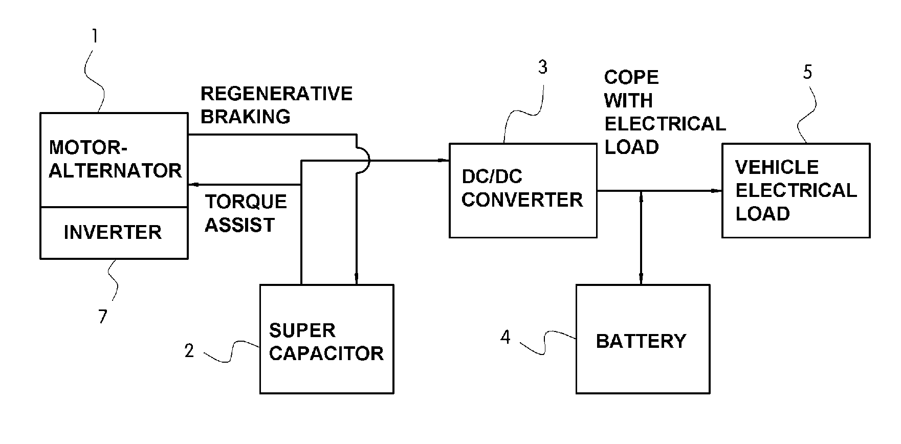
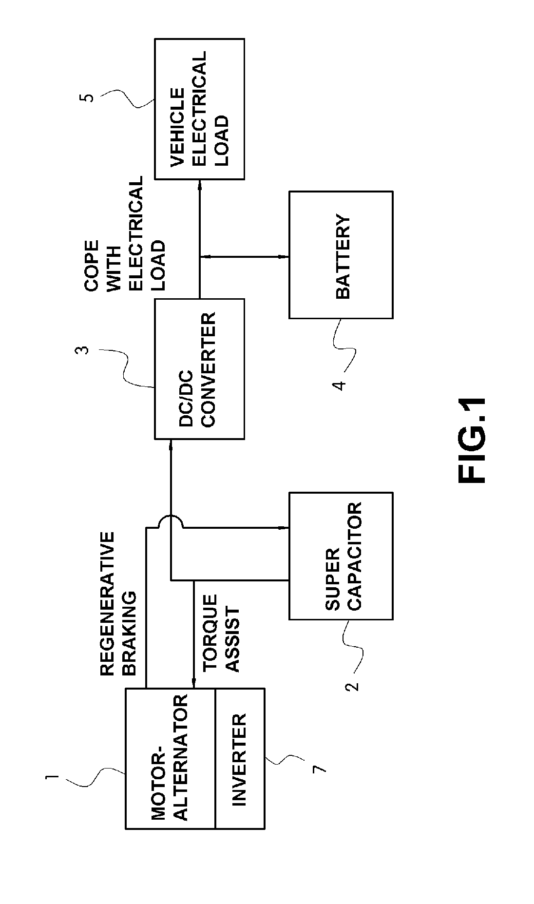
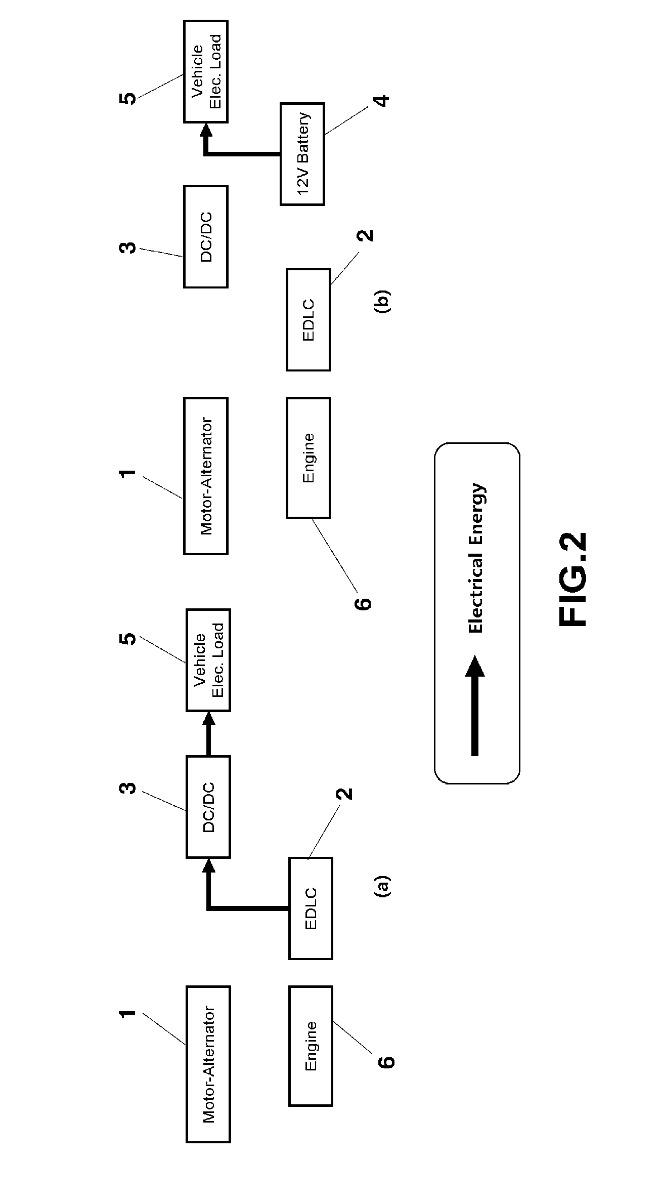
[0028]FIGS. 5 and 6 are schematic diagrams showing a mild hybrid system in accordance with an exemplary embodiment of the present invention, in which FIG. 5 shows a power transmission path when the electrical load used in the entire electrical load of a hybrid vehicle is smaller than a reference electrical load and FIG. 6 shows a power tr...


PUM


Abstract

A mild hybrid system according embodiments of the invention may include: a motor-alternator; an inverter for controlling electrical energy flow to and from the motor-alternator; an electrical energy storage for storing electrical energy generated by the motor-alternator; and a unidirectional DC/DC buck converter including a bypass means for providing a physical connection between the motor-alternator and a vehicle electrical load. With the system, the manufacturing cost can be reduced, packaging process can be simplified, and an additional cooling device is not required.

Description

CROSS-REFERENCE TO RELATED APPLICATION[0001]This application claims under 35 U.S.C. §119(a) the benefit of Korean Patent Application No. 10-2009-111173 filed Nov. 17, 2009, the entire contents of which are incorporated herein by reference.BACKGROUND[0002](a) Technical Field[0003]The present disclosure relates to a mild hybrid system and a method for controlling the same, which can improvement fuel efficiency.[0004](b) Background Art[0005]Demands for environment-friendly vehicles has been increased One of the attempts to meet the demands is to provide a mild hybrid system. In general, the mild hybrid system includes an engine and a motor-alternator connected to the engine. The motor-alternator, as a starter motor, receives drive power through an inverter to assist the power of the engine. On the other hand, the motor-alternator, as a generator, generates electricity using energy generated during braking to supply the electricity to a vehicle electrical load.[0006]FIG. 1 is a schemati...

Claims


Application Information

Patent Timeline
Patent Type & Authority Applications(United States)
IPC IPC(8): B60W20/00B60L50/10B60L50/16
CPCB60K6/485Y02T10/70B60W30/18127Y02T10/6226Y02T10/6278B60L11/1861B60L2210/12Y02T10/7044Y02T10/7005Y02T10/705Y02T10/7233B60L11/02B60K6/28B60Y2400/114B60L7/14B60L11/005B60L11/14B60L15/2009B60L2240/12B60L2240/423Y02T10/7077Y02T10/7022Y02T10/7275Y02T10/642B60W20/00B60L50/40B60L50/16B60L58/20Y02T10/62Y02T10/64Y02T10/72Y02T10/7072B60K2006/268B60K6/26B60K6/20B60K6/42B60W20/15
Inventor LEE, JUN YONG
Owner HYUNDAI MOTOR CO LTD
Why Eureka
Try Eureka