Hydrodynamic bearing assembly and motor having the same

US20110115323A1Inactive Publication Date: 2011-05-19SAMSUNG ELECTRO MECHANICS CO LTD

Image

  • Hydrodynamic bearing assembly and motor having the same
  • Hydrodynamic bearing assembly and motor having the same
  • Hydrodynamic bearing assembly and motor having the same

Examples


Embodiment Construction

[0033]Exemplary embodiments of the present invention will now be described in detail with reference to the accompanying drawings. The invention may, however, be embodied in many different forms and should not be construed as being limited to the embodiments set forth herein. Rather, these embodiments are provided so that this disclosure will be thorough and complete, and will fully convey the scope of the invention to those skilled in the art.

[0034]In the drawings, the shapes and dimensions may be exaggerated for clarity, and the same reference numerals will be used throughout to designate the same or like components.

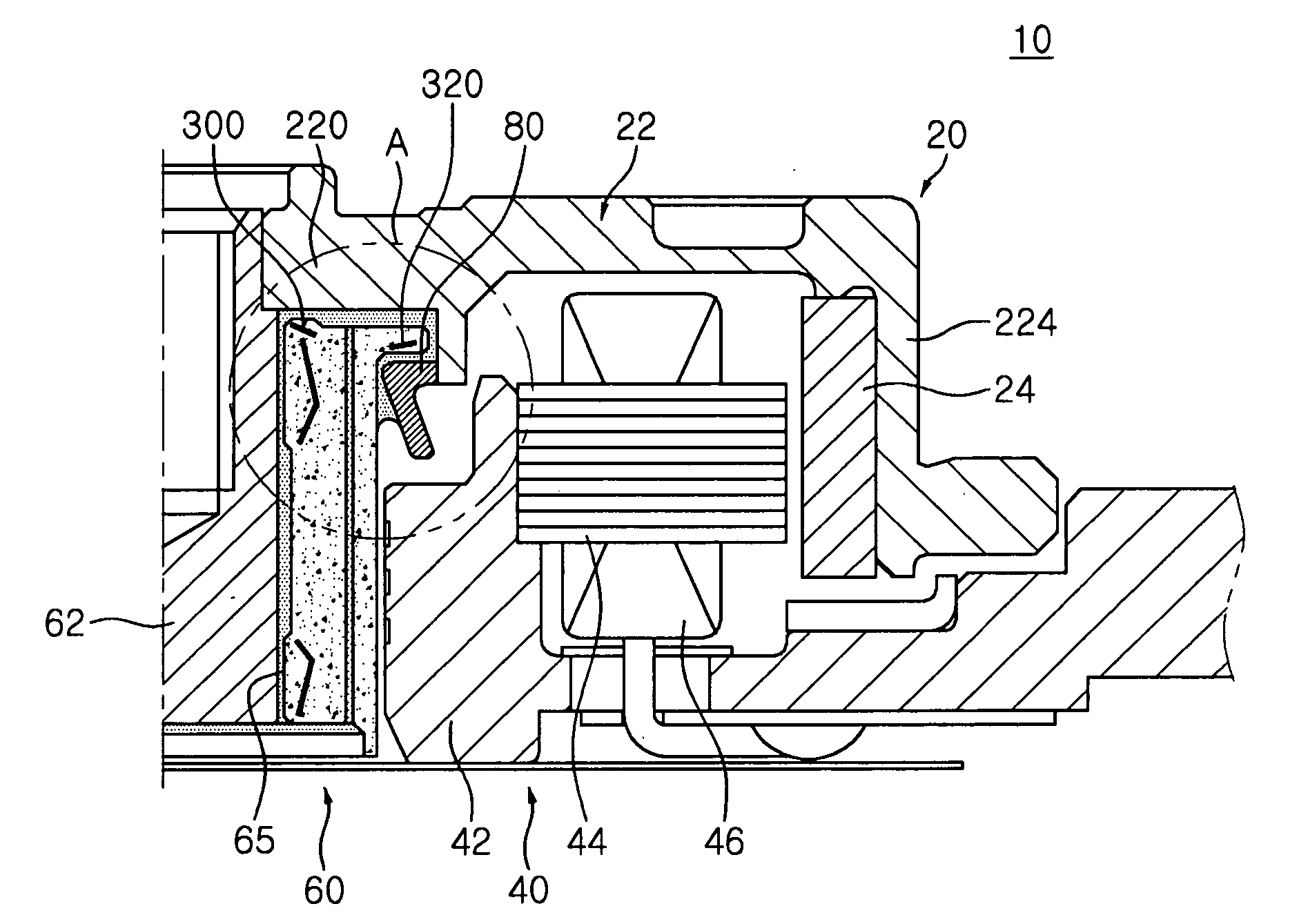
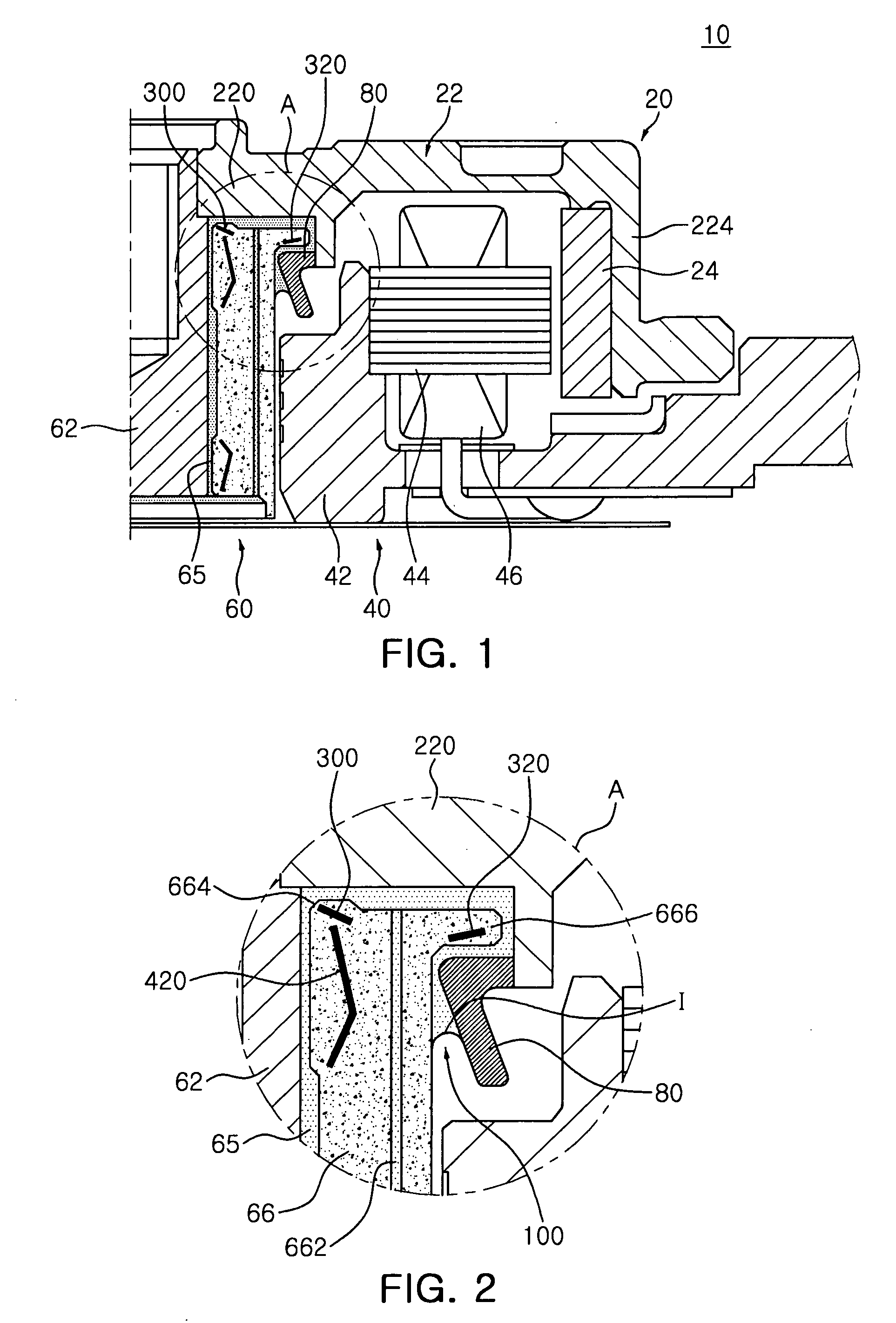
[0035]FIG. 1 is a schematic sectional view illustrating a motor according to an exemplary embodiment of the present invention. FIG. 2 is a schematic enlarged sectional view illustrating a portion A of FIG. 1.

[0036]Referring to FIGS. 1 and 2, a motor 10 according to this embodiment may include a hydrodynamic bearing assembly 60, a stator 40 and a rotor 20.

[0037]The hydro...


PUM


Abstract

There is provided a hydrodynamic bearing assembly including: a sleeve against which a shaft is supported so that an upper end of the shaft, being compressed and inserted into a hub base of a rotor case, protrudes upwardly in an axial direction; a first thrust dynamic pressure generating part formed in at least one of a protrusion and the hub base corresponding to the protrusion, the protrusion being formed at an end of the sleeve along an inner diameter direction; and a second thrust dynamic pressure generating part formed around a protruding end portion of the sleeve, the protruding end portion facing an upper portion of a stopper part in the axial direction and the stopper part rotating together with the rotor case. Also, an oil sealing part has an oil interface between an outer circumferential surface of the sleeve along an outer diameter direction and an inner surface of the stopper part.

Description

CROSS-REFERENCE TO RELATED APPLICATIONS[0001]This application claims the priority of Korean Patent Application No. 10-2009-0112267 filed on Nov. 19, 2009, in the Korean Intellectual Property Office, the disclosure of which is incorporated herein by reference.BACKGROUND OF THE INVENTION[0002]1. Field of the Invention[0003]The present invention relates to a hydrodynamic bearing assembly and a motor having the same, and more particularly, to a hydrodynamic bearing assembly having thrust dynamic pressure generating parts formed in a lower portion of an exterior end of a sleeve along an outer diameter direction thereof and in an upper portion of a protrusion at an end of the sleeve along an inner diameter direction thereof to allow for a reduction in starting friction torque in a motor without a reduction in the lifting force of the motor, and the motor having the hydrodynamic bearing assembly.[0004]2. Description of the Related Art[0005]A small-sized spindle motor, used in a recording d...

Claims


Application Information

Patent Timeline
19 May 2011
Publication
US20110115323A1
IPC
H02K7/08; F16C32/06
CPC
H02K5/1675; F16C17/107; H02K5/16; H02K5/167
Inventors
JANG, HO KYUNG; LIM, YOUNG HWAN