Real-time embedded visible spectrum light vision-based human finger detection and tracking method

a technology of visible spectrum light and tracking method, which is applied in the direction of instruments, color televisions, television systems, etc., can solve the problems of requiring a significant amount of computing power and storage, unable to perform the actions directly at the projection surface area with the fingers of presenters, and executing on large, expensive computer systems in non-real-time fashion

Inactive Publication Date: 2011-05-19
VISIONBRITE TECH
View PDF17 Cites 55 Cited by
  • Summary
  • Abstract
  • Description
  • Claims
  • Application Information

AI Technical Summary

Benefits of technology

[0005]One aspect provides a method. In one embodiment, the method includes capturing images of a human finger in the projection area monitored within the field of view (FOV) of a camera of an image capture device. The method further includes processing a first one of the images to detect a presence of a human finger, assigning a position of the presence of the finger tip, tracking movement of the finger as part of a human hand, generating a command based on the tracked movement of the finger within the FOV and communicating the presence, position and command to an external apparatus. The processing of the first one of the images to determine the presence of the human finger is completed by an image processor of the image capture device. The assignment of a position of the presence

Problems solved by technology

These conventional recognition methods process a small amount of finger feature data and usually execute on large, expensive computer systems in a non-real-time fashion.
To recognize a human finger out of complex backgrounds, tracking finger movement and interpreting finger movements into predefined gesture identification hav

Method used


Image

  • Real-time embedded visible spectrum light vision-based human finger detection and tracking method
  • Real-time embedded visible spectrum light vision-based human finger detection and tracking method
  • Real-time embedded visible spectrum light vision-based human finger detection and tracking method

Examples


embodiment 100

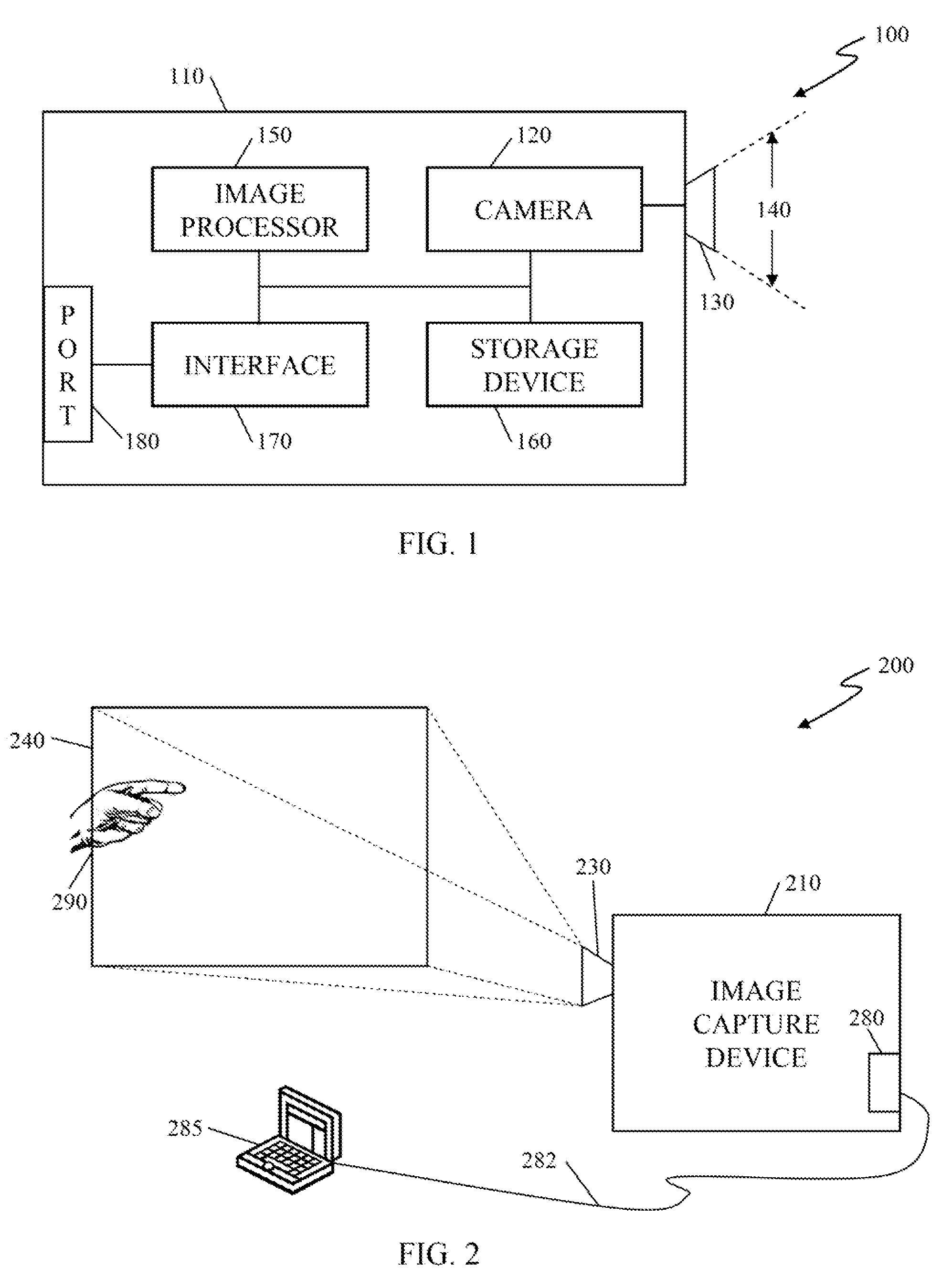
[0016]FIG. 1 illustrates an embodiment 100 of an image capture device 110. The image capture device 100 includes a camera 120, a lens 130, an image processor 150, a storage device 160, an interface 170 and an external communication port 180. The camera 120 is coupled to the lens 130 and captures an image in a field of view (FOV) 140. The camera 120 couples to the image processor 150 and the storage device 160. Images captured by the camera 120 are stored in the storage device 160 in conventional manners and formats. The interface 170 is coupled to the image processor 150 and the external communication port 180. The external communication port 180 supports known and future standard wired and wireless communication formats such as, e.g., USB, RS-232, RS-422 or Bluetooth®. Image processor 150 is also coupled to the storage device 160 to store certain data described below. The operation of various embodiments of the image capture device 110 will now be described. In other embodiments of...

embodiment 300

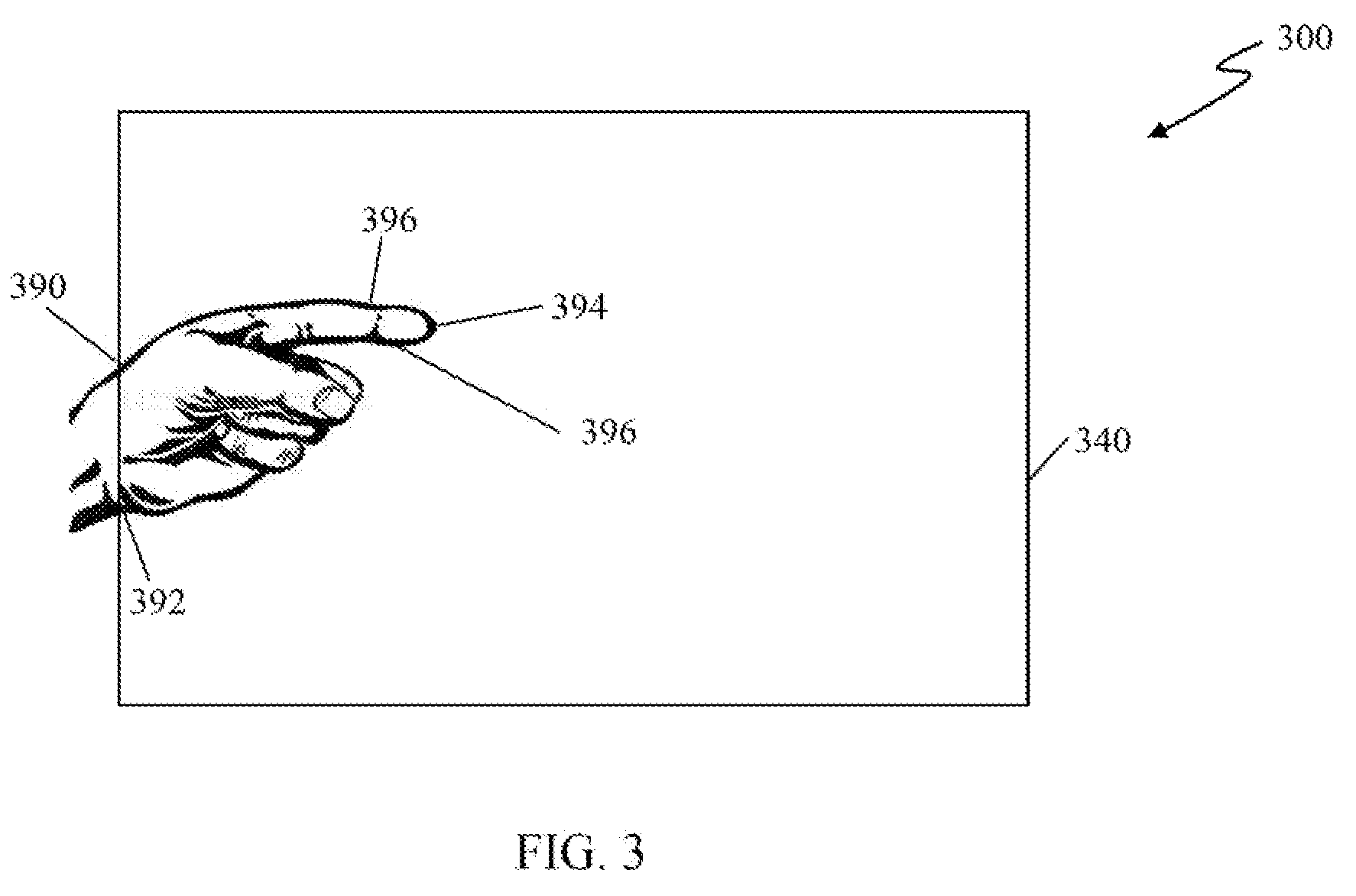
[0018]FIG. 3 illustrates in further detail the finger as part of human hand 290 in the FOV 240 of FIG. 2. An embodiment 300 illustrated in FIG. 3 illustrates a finger as part of human hand 390 in an FOV 340. The image capture device 210 of FIG. 2 (not shown) searches for a first contour line 392 of the hand 390 that starts at a border of the FOV 340. Second contour lines 396 are contour lines of each edge of a finger 394 of the hand 390. The first contour line 392 and the second contour lines 396, as discussed below, help the image capture device 210 determine a presence of human finger as part of a human hand 390 in the FOV 340.

[0019]FIGS. 4-6 illustrate an embodiment of a method the image capture device 110 / 210 may use to determine a presence and position of the human finger as part of a human hand 390 in the FOV 340. FIG. 4 illustrates a first portion 400 of a flow diagram of a method used by the image capture device 110, 210 to determine a presence and position of a finger in an...

embodiment 800

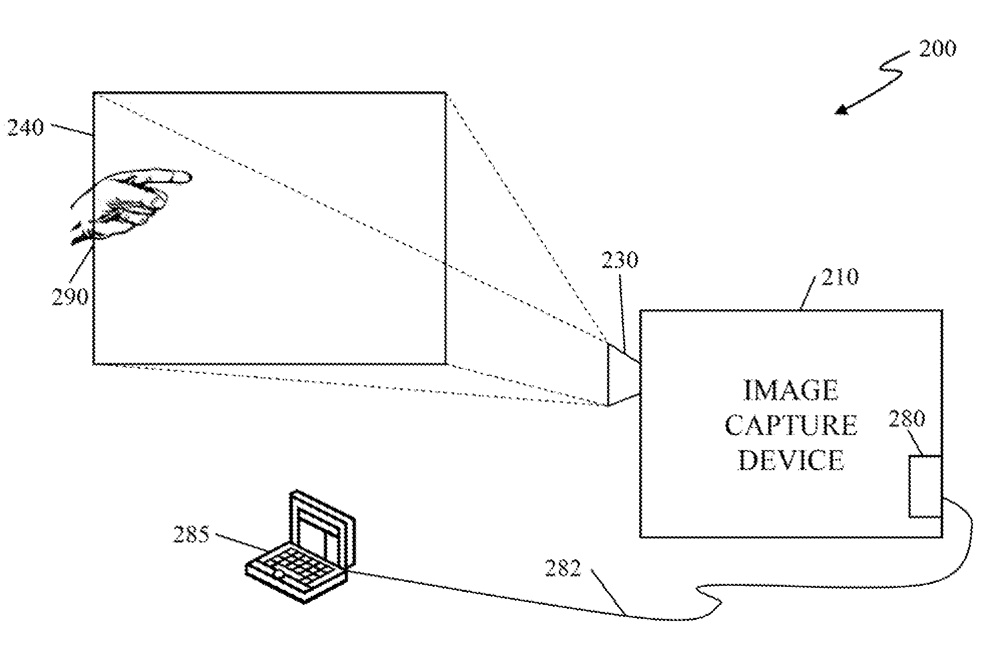
[0028]FIG. 8 illustrates an embodiment 800 of the example of a presenter described above. The embodiment 800 includes an image capture device and an external apparatus (not shown), such as the image capture device 210 and the conventional laptop computer 285 depicted in FIG. 2. The external apparatus either includes or interfaces to a projector that displays an object 898, such as a Microsoft PowerPoint® object, on a screen. The screen with the displayed object 898 is in an FOV 840 of the camera of the image capture device. The image capture device detects the presence and position of a finger tip 890 of the presenter in the FOV 840 and transmits it to the conventional laptop computer. The conventional laptop computer associates the position of the finger tip 890 of the presenter with a position of the object 898. The image capture device then tracks a movement of the finger tip 890 of the presenter (move up, move down, quickly curl the finger and stick out again, stay at a position...


PUM


Abstract

In one aspect there is provided an embodiment of an image capture device comprising a camera, an image processor, a storage device and an interface. The camera is configured to capture images in visible spectrum light of a human finger as part of a human hand in a field of view (FOV) of the camera. The image processor is configured to process a first one of the images to detect a presence of the finger. The image capture device is configured to detect the position of the presence of the finger tip, track movement of the finger tip within the FOV by processing at least a second one of the images and generate a command based on the tracked movement of the finger within the FOV. The method does not require any pre-detection training sequence with said finger prior to finger detection, and does not require the finger to be in specific relative angle or finger orientation in said FOV. If the human hand is holding a “finger” like object, such as a pen or stick, such object will be recognized as finger and the tip of the object will be recognized as finger tip and position is also detected. The interface is configured to transmit the detection of the presence of the finger, the assigned position of the finger tip and the command to an external apparatus.

Description

TECHNICAL FIELD[0001]This application is directed, in general, to an image capture device working within visible light spectrum and a method of detecting a presence of a human finger in a projection area monitored within the field of view of the image capture device, enables interactive control to projection contents.BACKGROUND[0002]Real-time vision-based human finger recognition has typically been focused on fingerprint recognition and palm print recognition for authentication applications. These conventional recognition methods process a small amount of finger feature data and usually execute on large, expensive computer systems in a non-real-time fashion. To recognize a human finger out of complex backgrounds, tracking finger movement and interpreting finger movements into predefined gesture identification have conventionally been limited by capabilities of imaging systems and image signal processing systems and typically involve a database for pattern matching, requiring a signi...

Claims


Application Information

Patent Timeline
IPC IPC(8): H04N7/18
CPCG06K9/00335G06V40/20
Inventor FAN, WENSHENGTANG, WEIYI
Owner VISIONBRITE TECH
Why Eureka
Try Eureka