Diaphragm and loudspeaker using the same

a technology of diaphragms and loudspeakers, applied in the direction of transducer diaphragms, instruments, transducer details, etc., can solve problems such as audible distortion

Active Publication Date: 2011-05-19
TSINGHUA UNIV +1
View PDF28 Cites 14 Cited by
  • Summary
  • Abstract
  • Description
  • Claims
  • Application Information

AI Technical Summary

Problems solved by technology

However, when the input power is increased to certain levels, the typi...

Method used


Image

  • Diaphragm and loudspeaker using the same
  • Diaphragm and loudspeaker using the same
  • Diaphragm and loudspeaker using the same

Examples


Embodiment Construction

The disclosure is illustrated by way of example and not by way of limitation in the figures of the accompanying drawings in which like references indicate similar elements. It should be noted that references to “an” or “one” embodiment in this disclosure are not necessarily to the same embodiment, and such references mean at least one.

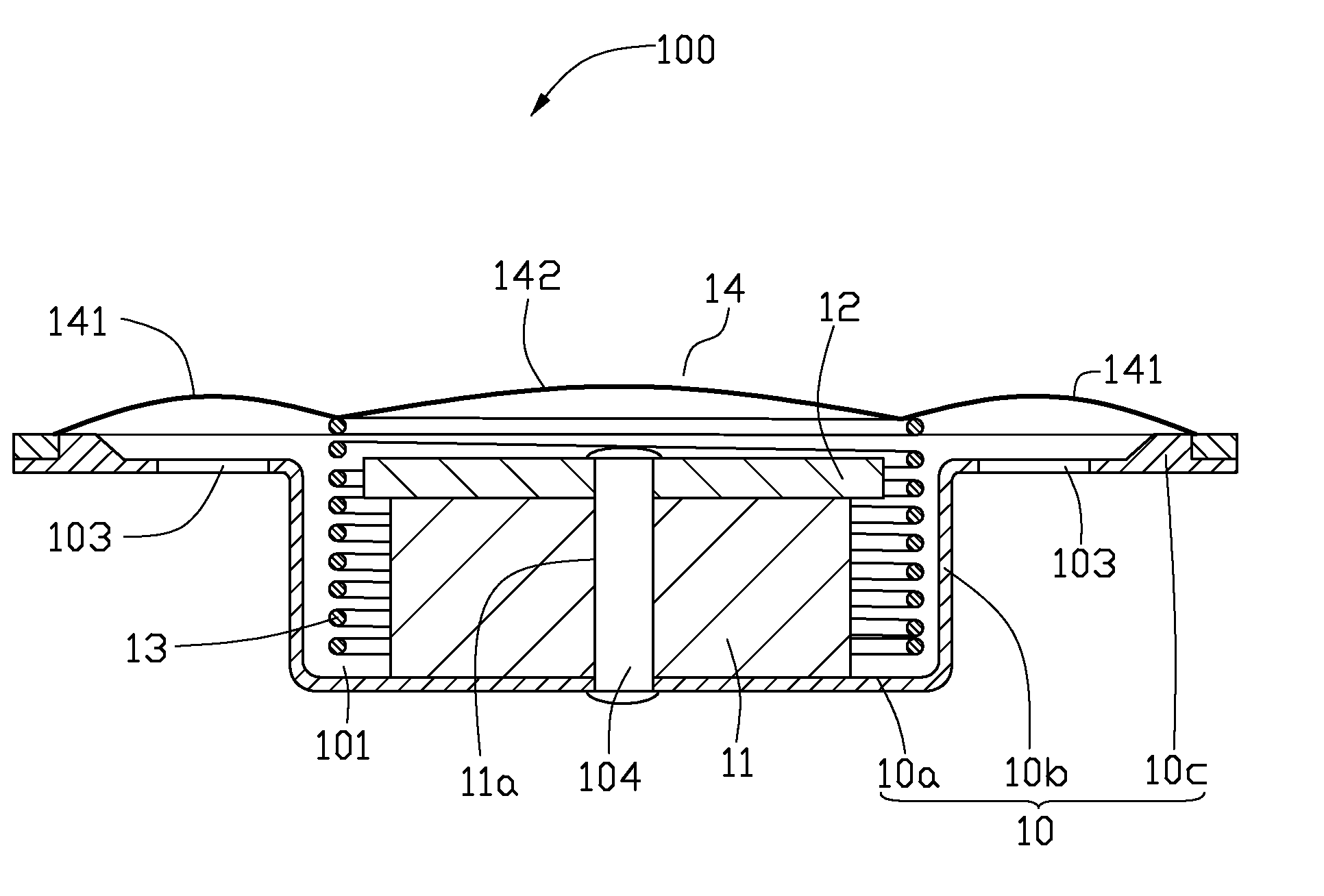
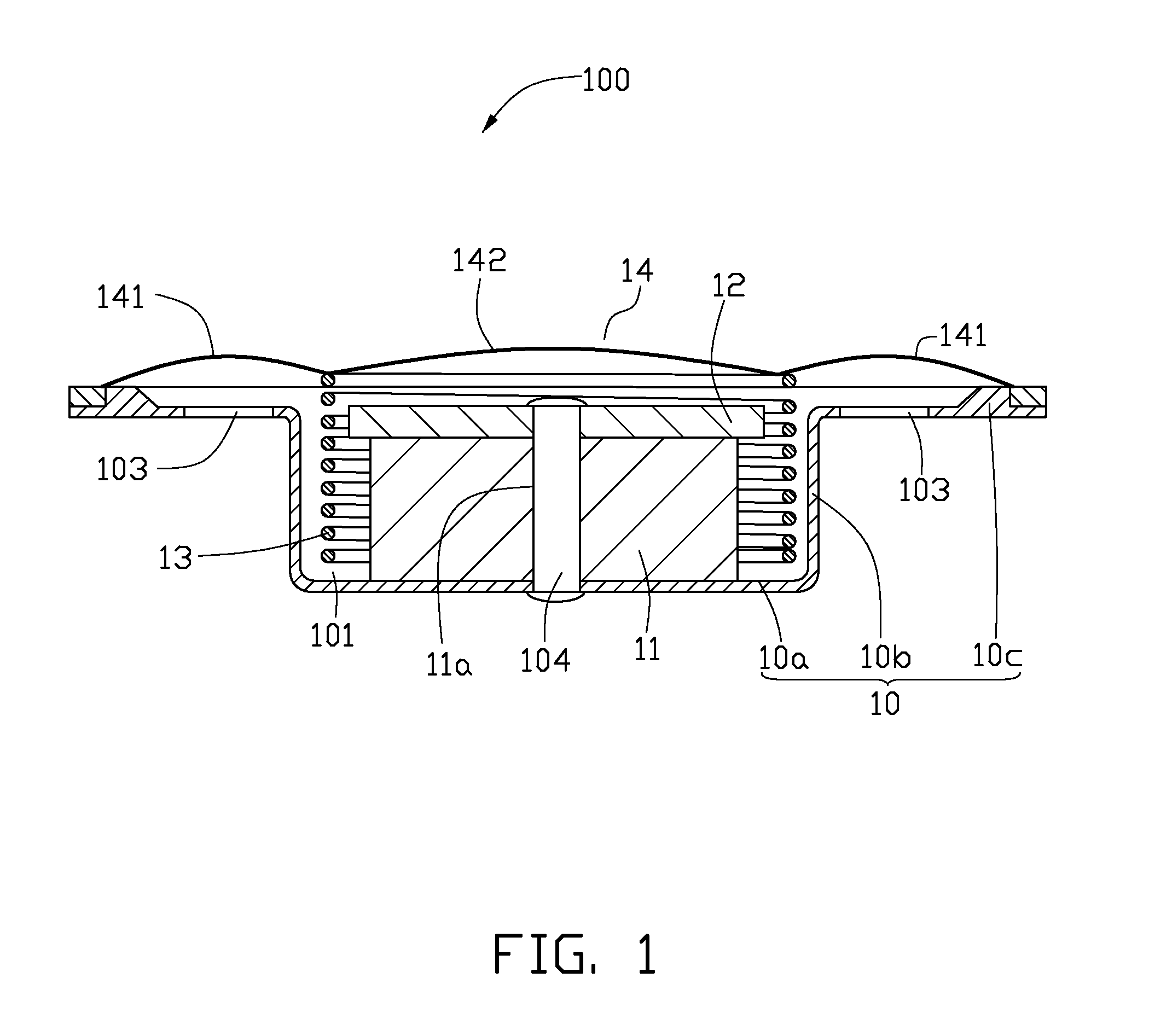
Referring to FIG. 1, an embodiment of a loudspeaker 100 comprises a frame 10, a magnet 11, an installing plate 12, a voice coil 13 and a diaphragm 14.

The frame 10 can be made by pressing a round metal plate. The frame 10 comprises a bottom plate 10a, a sidewall 10b and a flange 10c. The sidewall 10b extends upwardly from a periphery of the bottom plate 10a. The sidewall 10b and the bottom plate 10a together define a chamber 101 having an opening opposite to the bottom plate 10a. The flange 10c extends outwardly substantially perpendicularly from a top periphery of the sidewall 10b. A plurality of vent holes 103 is defined through the flange 10c and fac...


PUM


Abstract

A diaphragm includes a central portion and an edge portion around the central portion. The central portion includes a plurality of carbon nanotubes therein. The central portion is a carbon nanotube structure or a carbon nanotube composite structure. A loudspeaker using the diaphragm is also disclosed. The loudspeaker includes the diaphragm and a voice coil connected to the diaphragm. The voice coil is connected to an outer periphery of the central portion or a joint portion between the central portion and the edge portion.

Description

CROSS-REFERENCE TO RELATED APPLICATIONSThis application claims all benefits accruing under 35 U.S.C. §119 from China Patent Application No. 200910109831.1, filed on Nov. 11, 2009, in the China Intellectual Property Office, the disclosure of which is incorporated herein by reference.BACKGROUND1. Technical FieldThe present disclosure relates to diaphragms and loudspeakers and, particularly, to a diaphragm based on carbon nanotubes and a loudspeaker using the same.2. Description of Related ArtA loudspeaker is an acoustic device transforming received electric signals into sounds. There are different types of loudspeakers that can be categorized by their working principle, such as electro-dynamic loudspeakers, electromagnetic loudspeakers, electrostatic loudspeakers, and piezoelectric loudspeakers. Among the various types, the electro-dynamic loudspeakers have simple structures, good sound qualities, low costs, and are most widely used.The electro-dynamic loudspeaker typically includes a...

Claims


Application Information

Patent Timeline
IPC IPC(8): H04R9/06H04R7/00
CPCH04R7/125H04R2307/025H04R2307/023H04R7/127
Inventor WANG, JIA-PINGLIU, LIANG
Owner TSINGHUA UNIV
Why Eureka
Try Eureka