Retractable Substance Dispenser

a dispenser and dispenser technology, applied in the field of cosmetic substances dispensers, can solve the problems of inability to remove or replace the lids, inability to protect the applicator, and waste of contained substances through inadvertent expulsion into the lids, etc., and achieve the effect of protecting the applicator

Inactive Publication Date: 2011-05-19
CARROLL CRAIG +1
View PDF14 Cites 43 Cited by
  • Summary
  • Abstract
  • Description
  • Claims
  • Application Information

AI Technical Summary

Benefits of technology

[0010]It is a further object of the present application to provide a dispensing apparatus which allows elective expulsion of a substance while the applicator is exposed.
[0011]It is yet a further object of the present application to provide a dispensing apparatus without a detachable lid or cap, but which apparatus still protects the applicator from outside corruption.
[0012]It is yet a further object of the present application to provide a dispensing apparatus which may be used sufficiently with one hand.

Problems solved by technology

One problem with this type of dispenser is that a contained substance can be wasted through inadvertent expulsion into the lid.
Another problem with this type of dispenser arises through unmindful removal or replacement of the lid over the applicator since the substance invariably smears to the outside or the attaching portion of the lid.
When this happens, subsequent lid removal becomes increasingly difficult and the cosmetic substance unwittingly dirties the dispenser user's hands.
It is also difficult, with the traditional dispenser to maintain a sanitary applicator.
Another drawback for this type of dispenser is that it requires two hands to remove the lid.
Yet another problem is that the removable cap can easily be lost.
However, twisting is undesirable because it takes two hands and is time consuming.
Squeezing is undesirable because the amount of substance emitted is not easily metered, and can lead to substance waste because squeezing does not easily remove all the substance from the containing compartment.

Method used


Image

  • Retractable Substance Dispenser
  • Retractable Substance Dispenser
  • Retractable Substance Dispenser

Examples


embodiment 2

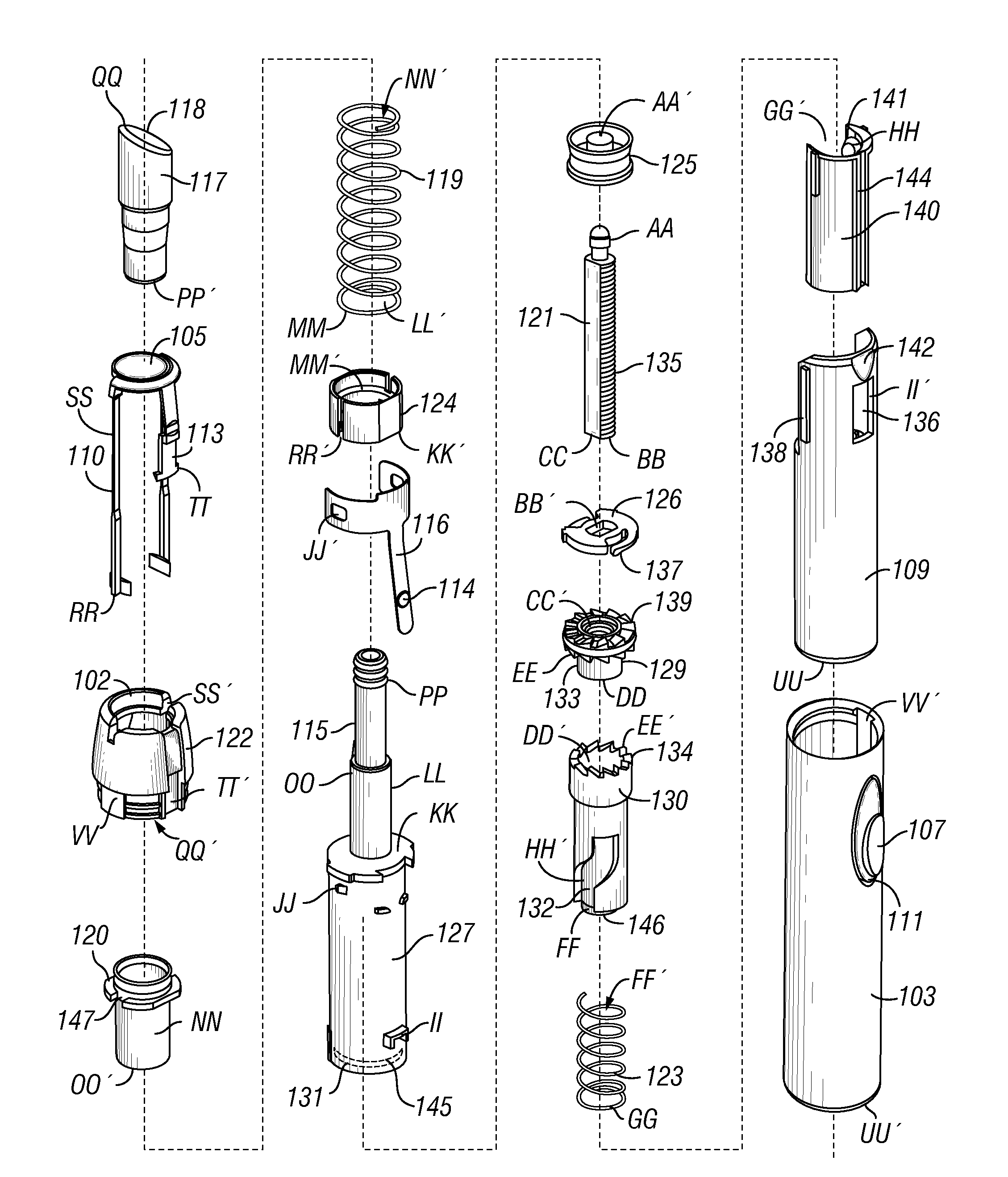
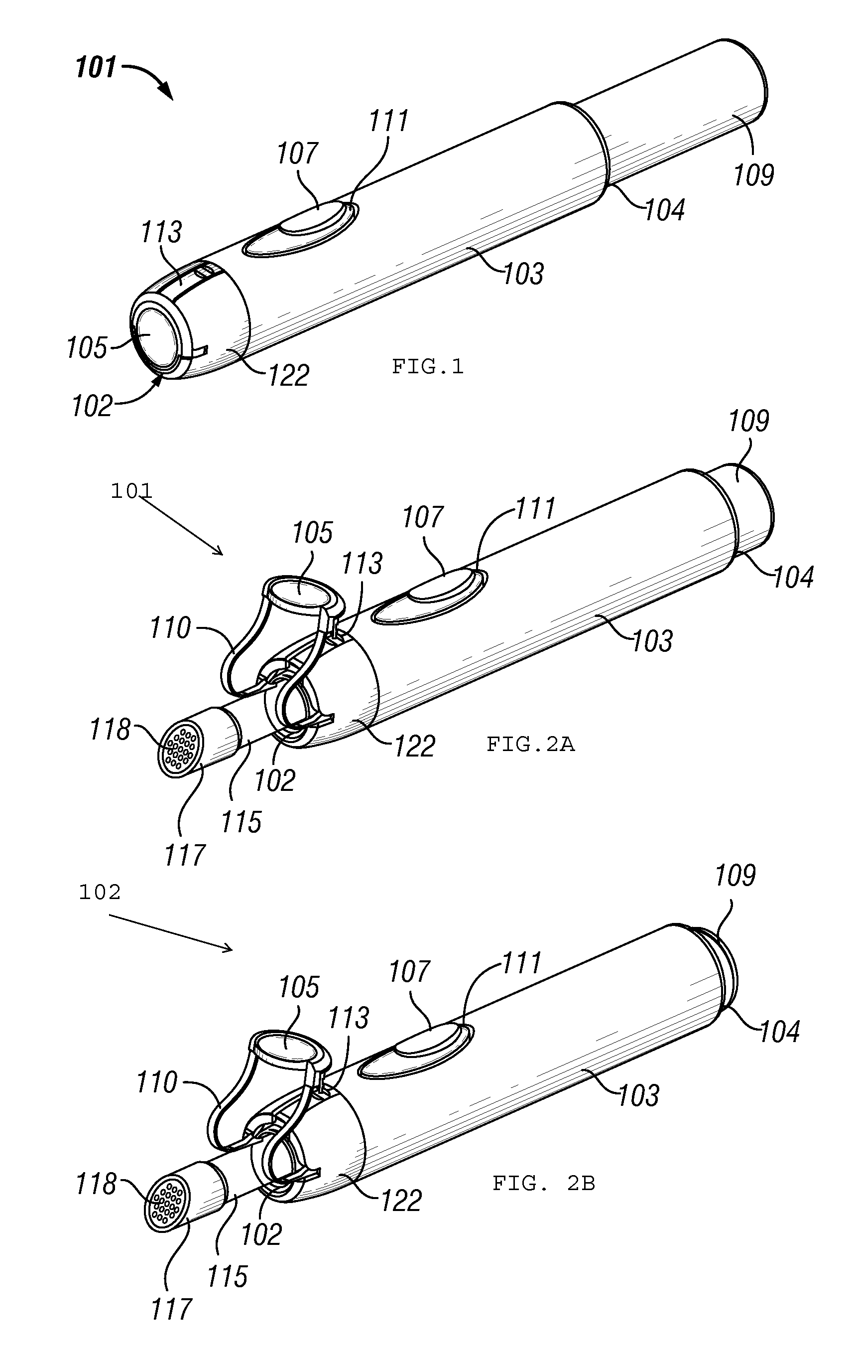
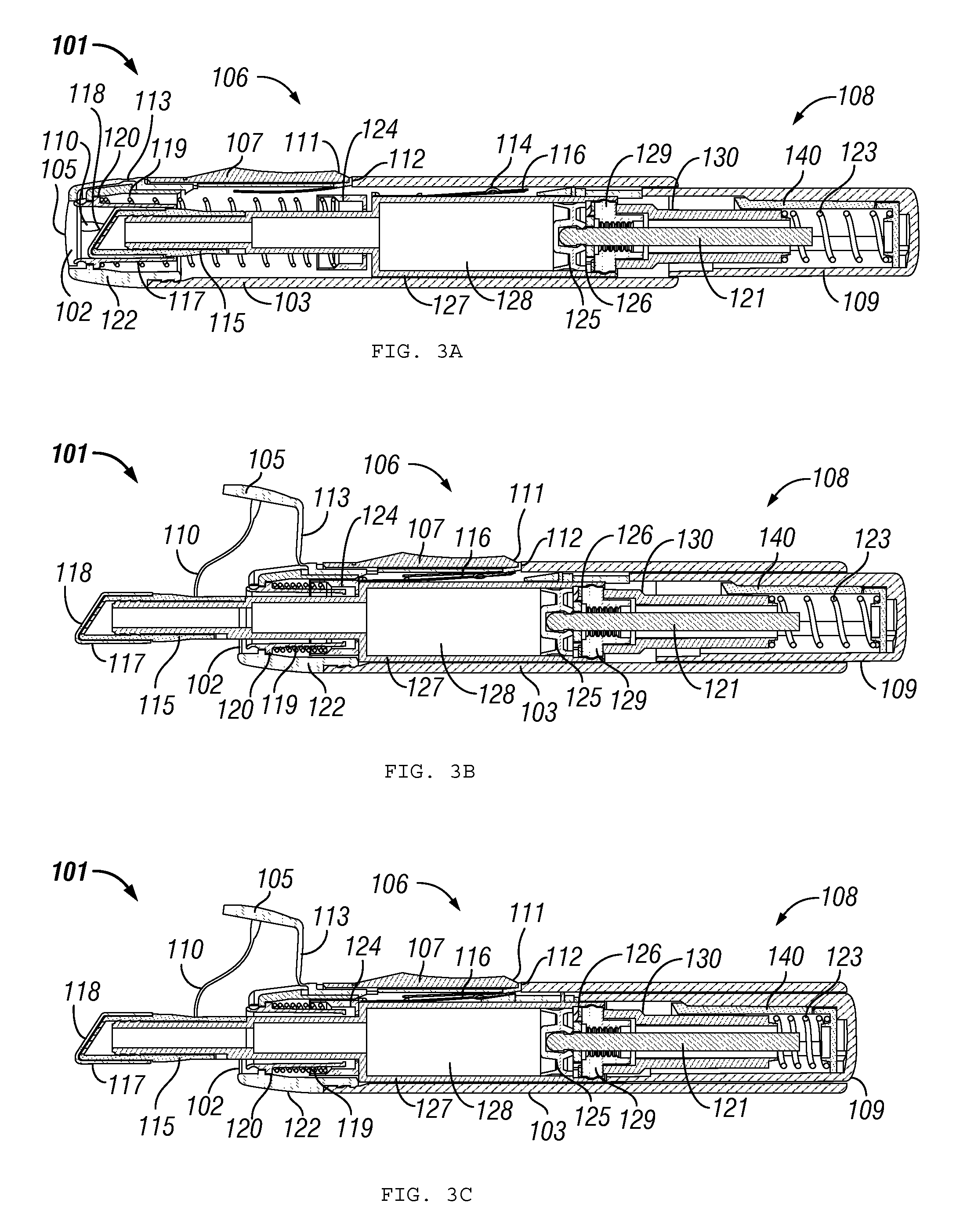
[0082]The dispenser 201 of the present application has a suitably retractable applicator 217 which may be electively exposed for applicator tip 218 use. Similar to the earlier preferred embodiment 2, elective transition from a closed to an open configuration is usually achieved through application of an initiating force which suitably activates the plunger 209 as a trigger, exposes anterior opening 202, and protrudes the applicator 217 from the dispenser 201. In most instances, the acting force on the plunger 209 will be generated by the user manually, for instance by a thumb or finger. The dispenser 201 typically has a natural tendency to revert from an open to a closed configuration. As discussed further herein, during transition from closed to open configurations, this tendency is normally continuously opposed to applicator 217 protrusion and plunger 209 activation. However, once the plunger 209 has been activated, the applicator 217 is suitably locked in external position and na...

embodiment 101

[0093]As mentioned above, until dispenser 201 is locked into the open configuration, the natural tendency will suitably invoke reversion to a closed configuration. Similar to the earlier disclosed embodiment 101, the dispenser 201 of the present application typically uses a suitable latching means to lock the open configuration when the applicator 217 has been protruded sufficiently from the anterior opening 202. The latching means may remove the natural tendency or suitably counteract its force. Similar to FIG. 3A and 3B (in view of FIG. 4), FIG. 9 (in view of FIG. 10) illustrates a latching means. FIG. 9 depicts a slot 216 set into the reservoir body 227 for interfacing with an edge 212 notched within the body 203 preferably below the lever 207 (note: the nub next to the slot 216 is a fulcrum point for the lever 207). Application of an axial initiating force at the plunger 109 butt, depresses the deactivated plunger 209 of FIG. 9, and moves the slot 216 toward edge 212 below lever...


PUM


Abstract

Disclosed is a cosmetic dispenser comprising a reservoir configured to hold a substance; an applicator selectively extendable or retractable from the dispenser; and, means for ejecting the substance in the reservoir through the applicator. Also disclosed are methods related to the use of the cosmetic dispenser.

Description

CROSS-REFERENCE TO RELATED APPLICATIONS[0001]This application claims the benefit of U.S. patent application Ser. No. 11 / 873,288 (filed Oct. 16, 2007) as a continuation in part thereof. The above identified application is hereby incorporated by reference.STATEMENT REGARDING FEDERALLY SPONSORED RESEARCH OR DEVELOPMENT[0002]N / ABACKGROUND OF THE INVENTION[0003]1. Field of Invention[0004]The present application is in the field of apparatus for dispensing cosmetic substances.[0005]2. Background of the Invention[0006]The ideal cosmetic dispenser is non-messy, portable, capable of storage, rapid delivery and easy application of a cosmetic substance. Typical cosmetic dispensers have a substance compartment whose contents may be emitted or placed onto an applicator for cosmetic application.[0007]Ordinarily, cosmetics dispensers come equipped with a detachable lid or cap that is pulled or twisted off from the dispenser to expose the applicator. The purpose of the lid is to protect the applicat...

Claims


Application Information

Patent Timeline
Patent Type & Authority Applications(United States)
IPC IPC(8): A45D40/26A45D40/00A46B11/02
CPCA45D34/04A45D2200/1018A45D2200/055
Inventor CARROLL, CRAIGARMSTRONG, STEVE
Owner CARROLL CRAIG
Why Eureka
Try Eureka