Method and system for augmenting a guidance system with a path sensor

a technology of path sensor and guidance system, which is applied in the direction of distance measurement, process and machine control, instruments, etc., can solve the problems of sensor not being able to produce useful offline distance measurement, erroneous measurement, and gap in information from the path sensor

Active Publication Date: 2011-05-19
TRIMBLE NAVIGATION LTD
View PDF18 Cites 36 Cited by
  • Summary
  • Abstract
  • Description
  • Claims
  • Application Information

AI Technical Summary

Benefits of technology

[0020]The method may include ignoring information from the path sensors if it is determined from the GNSS / Inertial system that the sensors are not in the desired row of the swath and are sensing a neighboring row. This avoids the vehicle or agricultural implement from being “snapped” into the wrong row.

Problems solved by technology

One major problem is when there is a gap in the information from the path sensors, for instance due to a gap in the planted row of crops due to a failure of some of the seeds to germinate.
In this situation the sensor is either unable to produce useful offline distance measurement for vehicle guidance or it simply produces erroneous measurements.
Another problem when using the path sensors alone is that absolute position, heading and speed information is not available.
Another disadvantage of path sensors is that many of them have a limited measurement range and may be affected by the heading of the vehicle / implement relative to the path.
This becomes particularly problematic when the vehicle has to steer to the next swath after a turn around from one swath to the next since the physical path references are typically interrupted at the ends of the fields.
However, even these enhancements to GPS leave undesirably large errors when considering the size and separation of typical furrows in a prepared field.
In addition to above-mentioned errors or inaccuracies in the GNSS system, there are off-sets that are introduced due to mechanical shortcomings of the vehicles and implements, e.g., failure of a towed implement to correctly track the path of the tractor pulling it.
In addition to mis-registrations and GNSS errors, physical characteristics of the land, e.g., obstructions such as trees or boulders, may force a vehicle path to deviate.

Method used


Image

  • Method and system for augmenting a guidance system with a path sensor
  • Method and system for augmenting a guidance system with a path sensor
  • Method and system for augmenting a guidance system with a path sensor

Examples


Embodiment Construction

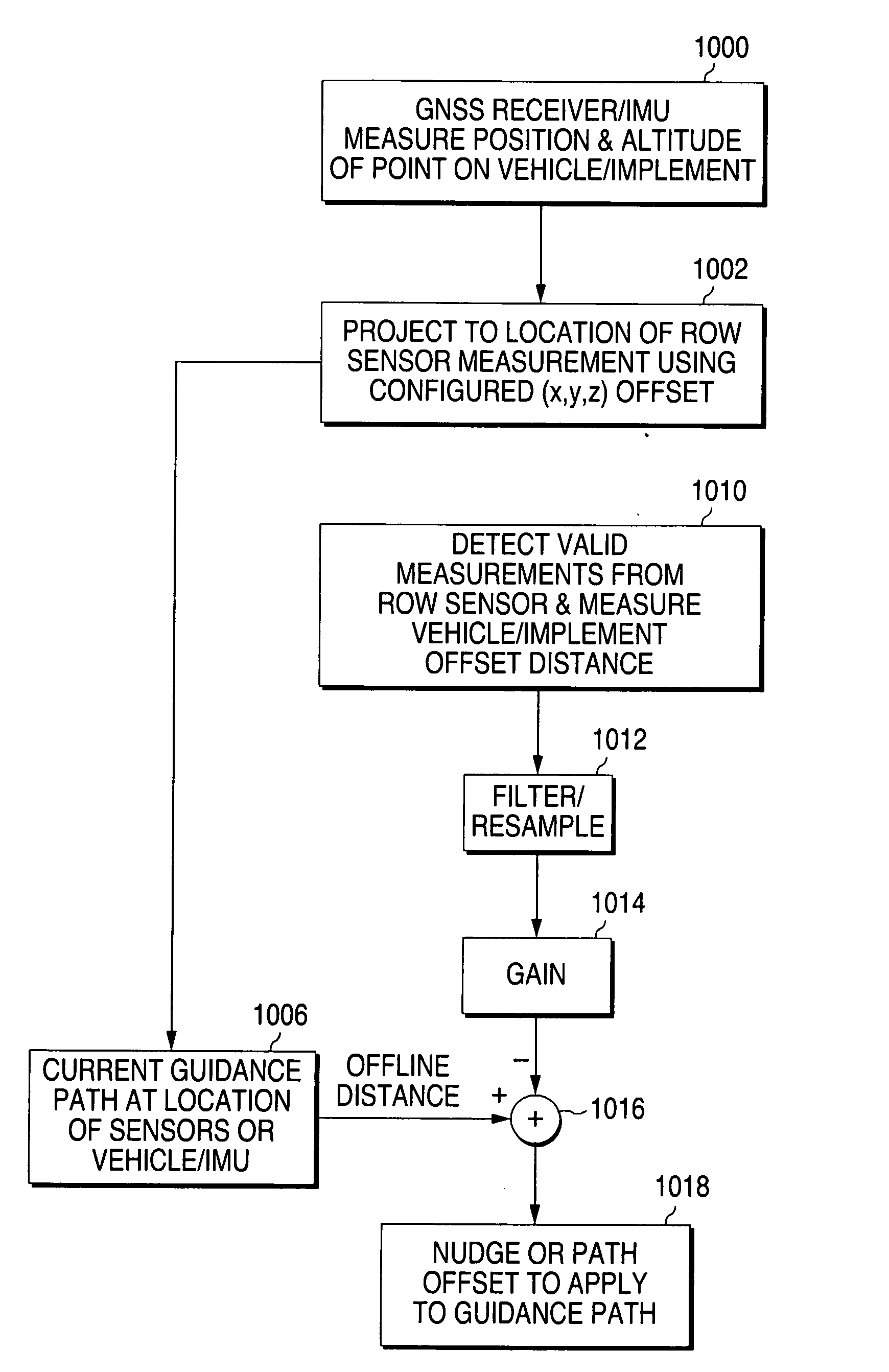
[0032]In one embodiment the present invention provides a vehicle guidance system, also referred to herein as an auto-nudging system, which makes use of a satellite based vehicle position monitoring system to provide vehicle path information and additional sensors to augment the path information. As will become clearer below, the introduction of the additional sensors also has the effect of improving satellite-based measurements (GNSS) or Inertial Sensor measurements, thereby reducing the performance capability requirements of the GNSS receiver or sensor to be used for the GNSS or Inertial Sensor. Also by providing vehicle guidance with respect to manually planted fields more accurate results can be obtained than when using GNSS or an Inertial Sensor system (also referred to herein as a GNSS / Inertial movement unit or GNSS / IMU) alone. One embodiment of such a system is shown as a block diagram in FIG. 13, in which a processor 1300 receives inputs from a GNSS receiver 1302, an IMU 1304...


PUM


Abstract

In an automatic vehicle position control system, such as a satellite-based agricultural implement steering system, the satellite-based steering information is adjusted with information obtained from one or more path sensors to facilitate the automatic nudging of the vehicle to take account of inaccurate tracking of the agricultural implement relative to its tractor, terrain variations, and inaccuracies in the satellite-based steering system.

Description

FIELD OF THE INVENTION[0001]The invention relates to the automatic control of a vehicle or agriculture implement. In particular it relates to the automatic positioning of agricultural vehicles and or implements in order to facilitate the tracking along pre-defined or pre-existing paths.BACKGROUND OF THE INVENTION[0002]It is common in the field of agriculture to make use of automation systems to help steer tractors and other agricultural land-working vehicles such as harvesters, sprayers and their attached implements. All of these types of farm equipment are referred to hereinafter as “mobile agricultural machines.” In the past, farm vehicles and guided implements have made use of sensors to help guide them along pre-defined or pre-existing swaths or rows. The swath width is the coverage width of the implement in use, and for crops planted in rows it is an integer multiple of the row spacing. These sensors, which will be referred to herein as path sensors, measure the offline distanc...

Claims


Application Information

Patent Timeline
Patent Type & Authority Applications(United States)
IPC IPC(8): G05D1/00
CPCG05D1/0227G05D1/0278G01C21/34A01B69/008G05D2201/0201
Inventor PEAKE, JOHN WILLIAMLANGE, ARTHUR F.
Owner TRIMBLE NAVIGATION LTD
Why Eureka
Try Eureka