
Evaporated Fuel Processing Device

a technology of evaporation fuel and processing device, which is applied in the direction of condensed fuel collection/return, charge feed system, non-fuel substance addition to fuel, etc., can solve the problems of canister pollution, and achieve the effect of reducing the pressure of evaporated fuel, reducing the energy (electric power) required for driving the pump for return, and efficient separation

Active Publication Date: 2011-05-26
AISAN IND CO LTD
View PDF4 Cites 8 Cited by
  • Summary
  • Abstract
  • Description
  • Claims
  • Application Information

AI Technical Summary

Benefits of technology

[0007]In view of the above-described circumstances, a topic of the present invention is to provide an evaporated fuel processing device that can suppress the sending of gas, that has a high concentration of evaporated fuel, to a canister and the polluting of the canister.
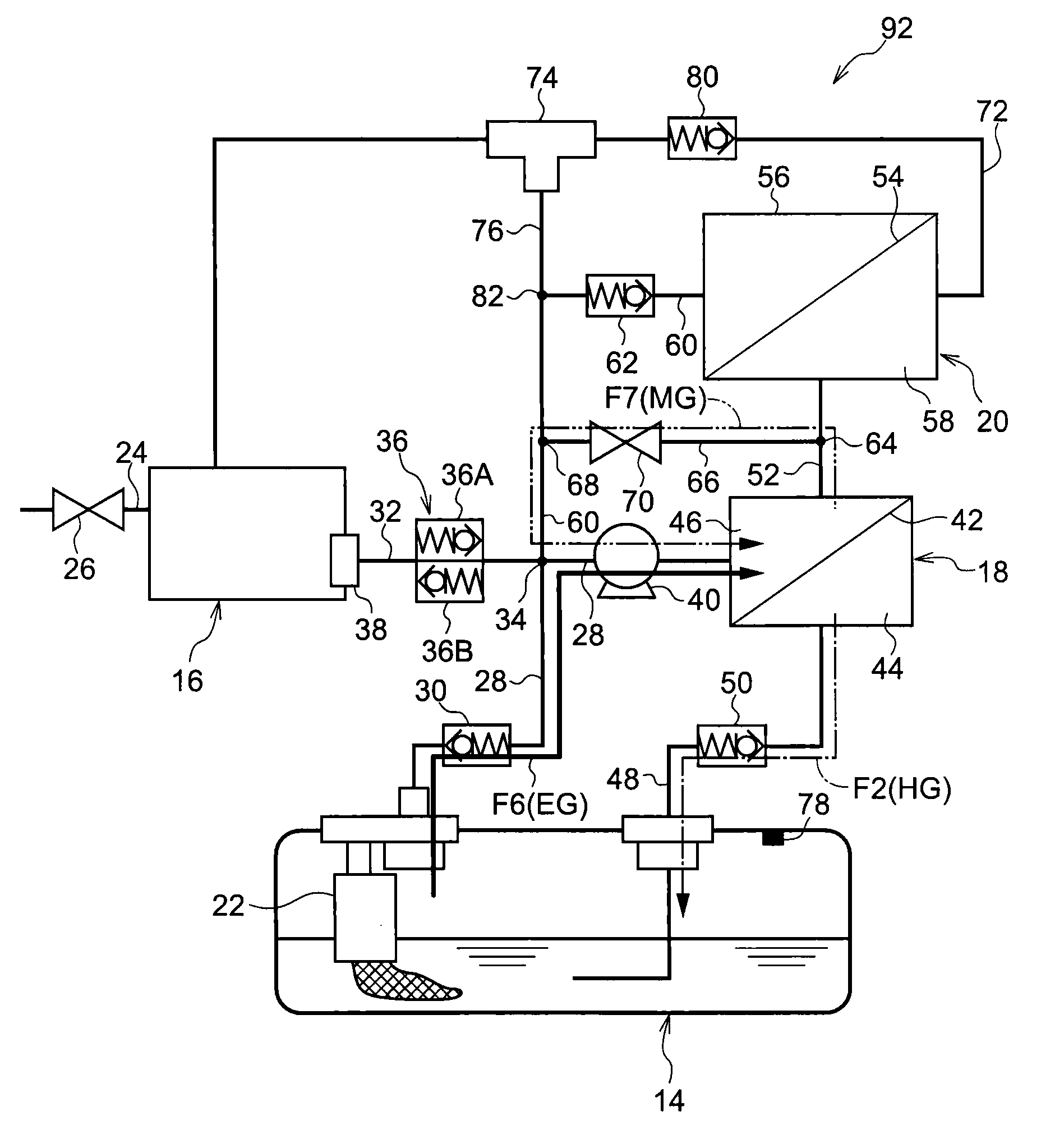
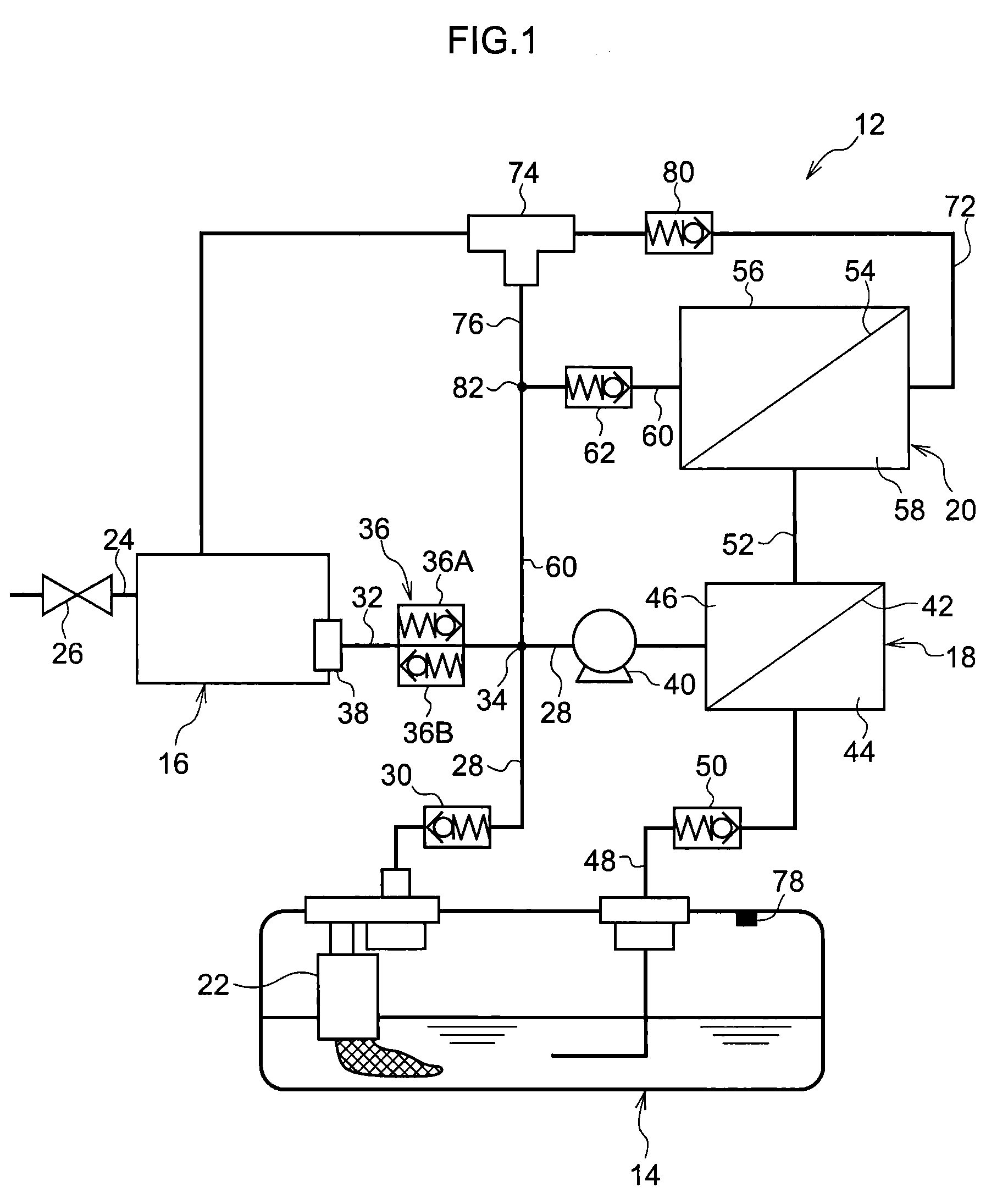
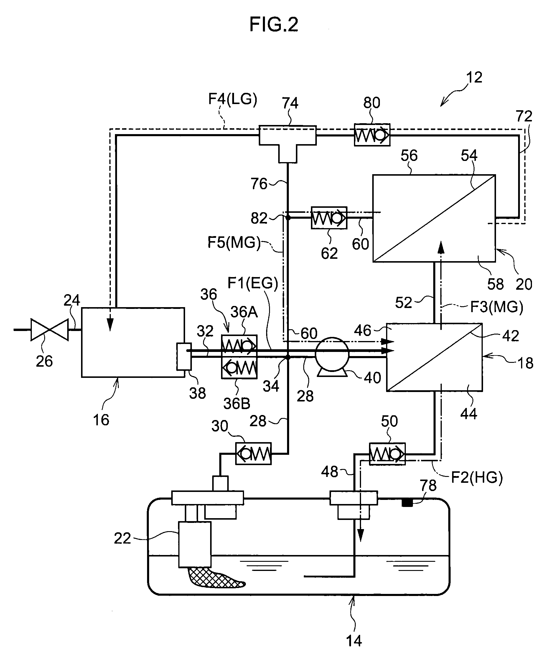
[0011]Further, by switching the switching valve to the side of the evaporated fuel return flow path and driving the pump for return, the gas, that contains the evaporated fuel existing within the purging flow path, can be returned to the first separating unit through the evaporated fuel return flow path. For example, even when low concentration gas stays within the purging flow path and becomes high concentration gas, this high concentration gas can be made into low concentration gas by using the first separating unit (and further using the second separating unit). By switching the switching valve to the purging flow path side and sending the low concentration gas that is generated in this way to the canister, purging of the evaporated fuel that is adsorbed within the canister can be carried out by using the low concentration gas. Gas that has become high concentration is not sent into the canister, and polluting of the canister can be suppressed.
[0013]Accordingly, as compared with a structure in which valves are provided respectively at the evaporated fuel return flow path and the purging flow path downstream of the branch portion, the single three-way valve suffices as the switching valve, and therefore, the structure can be simplified.
[0016]The evaporated fuel return flow path merges with the tank exhaust flow path at the upstream side of the sending pump, and the sending pump also serves as the returning pump. Further, a portion of the tank exhaust flow path also serves as a portion of the evaporated fuel return flow path. For these reasons, the structure of the evaporated fuel processing device can be simplified.
[0018]In the above-described structure, the medium gas return flow path merges with the tank exhaust flow path at the upstream side of the sending pump. Therefore, by opening the opening / closing valve and driving the sending pump, the medium concentration gas generated at the first separating unit is, without being sent to the second separating unit, introduced into the first separating unit again and can be separated or liquefied and recovered. Because the medium concentration gas is not sent to the second separating unit, the pressure of the evaporated fuel can be lowered by that much. The energy (electric power) required for driving the pump for return can be reduced, and evaporated fuel can be efficiently separated into high concentration gas and low concentration gas.
[0019]Due to the above-described structure, the present invention can suppress polluting of a canister due to vapor, whose concentration of evaporated fuel is high, being sent to the canister.

Problems solved by technology

Then, when the evaporated fuel processing device is started-up, the evaporated fuel that has become high concentration is sent to the canister, and the canister may be polluted.

Method used


Image

  • Evaporated Fuel Processing Device
  • Evaporated Fuel Processing Device
  • Evaporated Fuel Processing Device

Examples


Embodiment Construction

[0025]The schematic structure of an evaporated fuel processing device 12 of a first exemplary embodiment of the present invention is shown in FIG. 1. The evaporated fuel processing device 12 has a fuel tank 14, a canister 16, a first separating film unit 18, and a second separating film unit 20. A fuel pump 22 is provided at the fuel tank 14. Due to the fuel pump 22 being driven by an unillustrated ECU, fuel that is accommodated within the fuel tank 14 can be supplied to an unillustrated engine.

[0026]Active carbon that serves as an adsorbent is accommodated within the canister 16. The evaporated fuel that is generated within the fuel tank 14 can be adsorbed by the active carbon of the canister 16, and the adsorbed evaporated fuel can be purged.

[0027]One end of a vent pipe 24 is connected to the canister 16, and the other end of the vent pipe 24 is open to the atmosphere. A solenoid open valve 26, whose opening and closing is controlled by the unillustrated ECU, is provided at the ve...


PUM


Abstract

A solenoid switching valve is provided at a low concentration gas pipe that sends gas from a second separating film unit to a canister. A reflux pipe, that is branched-off from the low concentration gas pipe by the solenoid switching valve, merges with a medium concentration gas pipe that is from the second separating film unit, and further runs via a circulating pipe, and reaches a merge portion with a purge pipe from the canister. By switching the solenoid switching valve to the merge portion side and driving a purge pump that is provided at an exhaust pipe between the merge portion and a first separating film unit, gas, whose concentration has risen within the low concentration gas pipe, is sent to the first separating film unit, and is separated into high concentration gas HG and low concentration gas LG.

Description

RELATED APPLICATION[0001]This application claims priority under 35 USC 119 from Japanese Patent Application No. 2009-266747, filed on Nov. 24, 2009, the disclosure of which is incorporated by reference herein.BACKGROUND OF THE INVENTION[0002]1. Field of the Invention[0003]The present invention relates to an evaporated fuel processing device for processing evaporated fuel.[0004]2. Description of the Related Art[0005]As an evaporated fuel processing device for processing evaporated fuel that is generated in a fuel tank provided in a vehicle such as an automobile or the like, Japanese Patent Application Laid-Open (JP-A) No. 2004-353600 for example discloses a structure in which gas that flows-out from a canister is made to pass through two separating units in order, and the high concentration gas is returned to the fuel tank, and the low concentration gas is returned to the canister.[0006]In the structure disclosed in JP-A No. 2004-353600, the low concentration gas that is exhausted fr...

Claims


Application Information

Patent Timeline
Patent Type & Authority Applications(United States)
IPC IPC(8): F02M33/02
CPCF02M25/089F02M33/08F02M33/02
Inventor ASO, SHUICHINAGAI, TAKASHI
Owner AISAN IND CO LTD
Learn More