Heat exchanger network

Inactive Publication Date: 2011-05-26
AUTOKUHLER GMBH & CO KG
View PDF17 Cites 43 Cited by
  • Summary
  • Abstract
  • Description
  • Claims
  • Application Information

AI Technical Summary

Benefits of technology

[0011]In accordance with an embodiment of the present disclosure, the spacers are arranged in several parts made of two mutually spaced end pieces and at least two rails which connect the end pieces with each other. As a result of the multipart arrangement, the cuttings and thus also the material consumption in punching out the spacers can be reduced substantially. Moreover, the lengths of

Problems solved by technology

Such a configuration requires much mounting work due to the numerous different components and leads to comparatively high material costs and requires more space due to the additional attachment of the collecting chambers.
Heat exchanger grids of this kind also consist of numerous individual parts and are also problematic with respect to their positional stability unless additional or specially designed turbulator inserts or the like are provided between the plates.
Although the heat exchanger grids, as described above, and similar ones ensure

Method used


Image

  • Heat exchanger network
  • Heat exchanger network
  • Heat exchanger network

Examples


Example

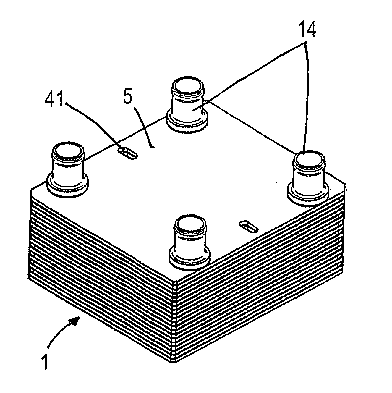
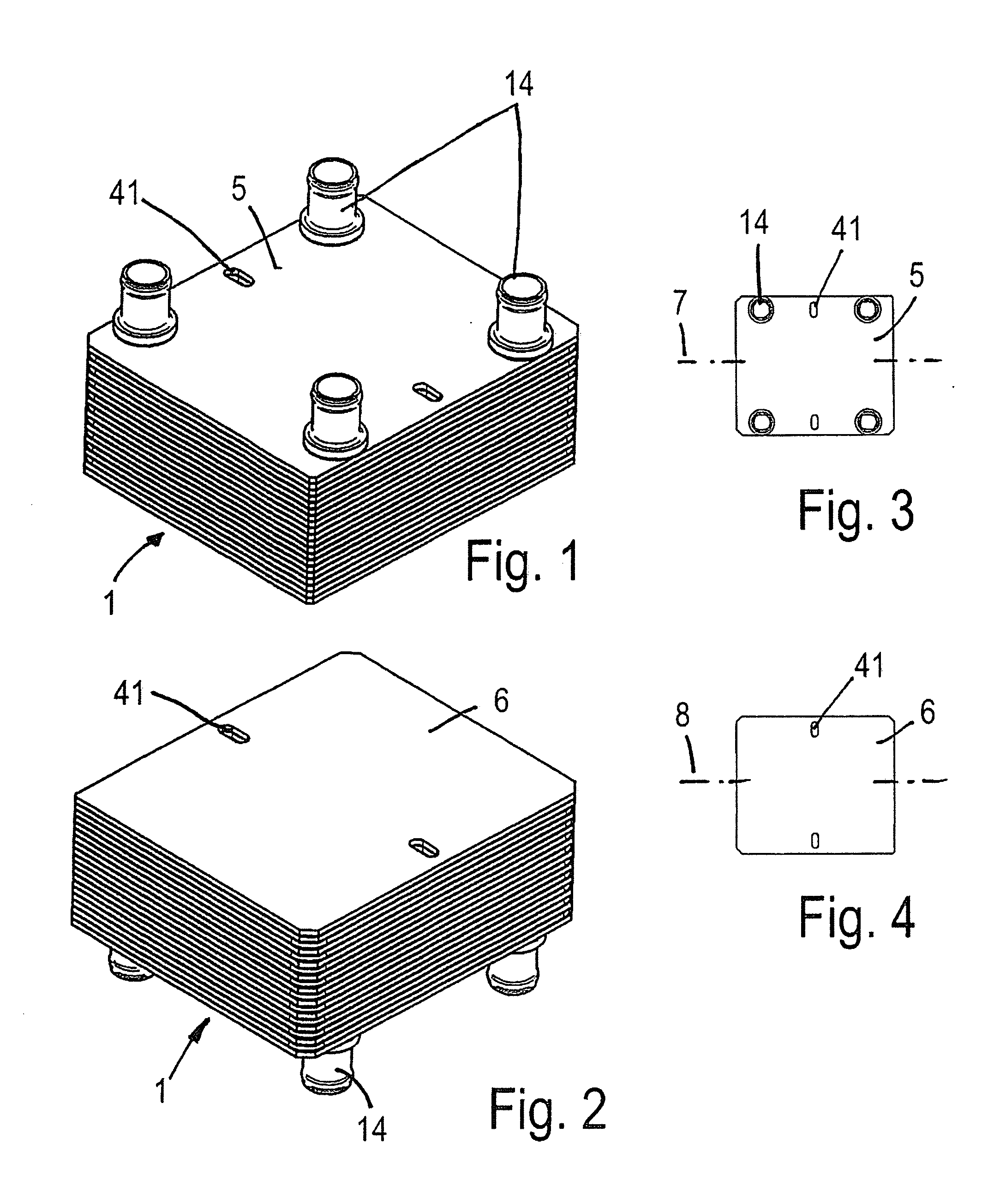
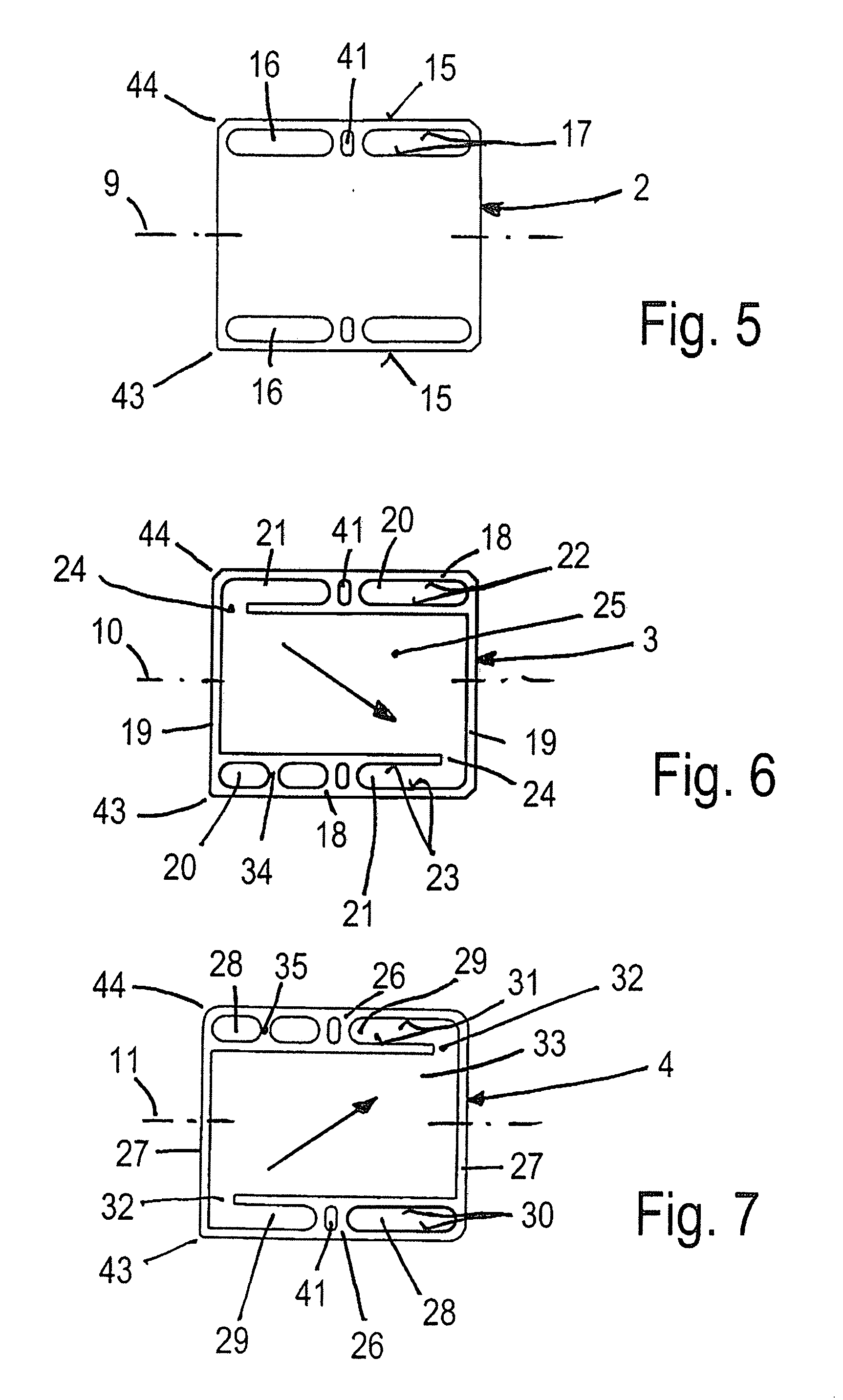
[0025]FIGS. 1 and 2 show a first embodiment of a heat exchanger grid, in accordance with the present disclosure. The grid comprises a stack 1 which includes stacked dividing plates 2, as shown in FIG. 5, and spacers 3 and 4, as shown in FIGS. 6 and 7, which spacers 3, 4 are arranged in an alternating manner between two dividing plates 2 each, and which stack is provided at the ends with end plates 5 and 6 as shown in FIGS. 3 and 4. The dividing plates 2, the spacers 3, 4 and end plates 5, 6 may have equally large and square or rectangular outer contours and longitudinal axes 7 to 11 which extend through their middle and, in the case of rectangular contours, extend parallel to their long rectangular side, as shown in FIGS. 3 to 7.

[0026]The end plates 5 and / or 6 are provided with inlet and / or discharge openings 12a to 12d, as shown in FIG. 8, on which connecting elements 14, in form of pipe sockets or the like, are placed in order to supply or discharge the media flowing through the h...


PUM


Abstract

A heat exchanger grid includes a stack including and arranged between end plates and further includes dividing plates and spacers arranged between the end plates to form sealed chambers for at least two heat exchange media. The end plates include one or both of inlet and outlet openings for the at least two media. The dividing plates including first passages aligned with the one or both of the inlet and outlet openings. The first passages are delimited by circumferentially enclosed edges and form collecting channels for the at least two media. The spacers include frames which are delimited circumferentially by rails and which spacers include second and third passages which are aligned at least partly with respect to the one or both of the inlet and outlet openings. The first, second, and third passages are arranged as slots with a part of the second and third passages being delimited by circumferentially enclosed edges and another part of the second and third passages including pass-through gaps facing toward the sealed chambers and except for the gaps, the second and third passages are enclosed.

Description

[0001]This application is a claims benefit of and priority to German Patent Application No. 20 2009 015 586.2, filed Nov. 12, 2009, the content of which application is incorporated by reference herein.BACKGROUND AND SUMMARY[0002]The present disclosure relates to a heat exchanger grid. The grid includes a stack of end plates and dividing plates, and spacers arranged between them for forming mutually sealed chambers for at least two heat exchange media.[0003]Heat exchanger grids are frequently built in plate design, for example, see DE 20 2004 011 489 U1, in that a stack is formed from plates and spacers which keep them apart and are provided in form of individual sections or rails. The stack comprises chambers which are sealed against each other and through which at least two heat-exchanging media flow, especially fluid ones. The various components of the stack are connected by soldering, for example, and are sealed against each other. The finished grid is then fastened by welding to...

Claims


Application Information

Patent Timeline
IPC IPC(8): F28F13/12F28D7/00
CPCF28D9/0075
Inventor PALM, HANS-JURGEN
Owner AUTOKUHLER GMBH & CO KG
Why Eureka
Try Eureka