Method for automatic bottom blowing control of converter
A bottom blowing control and converter technology, which is applied in the manufacture of converters, etc., can solve problems such as poor hardware operation and increased costs, and achieve the effects of reducing blowing time and material consumption, reducing operating intensity, and reducing production costs.
- Summary
- Abstract
- Description
- Claims
- Application Information
AI Technical Summary
Problems solved by technology
Method used
Image
Examples
Embodiment 1
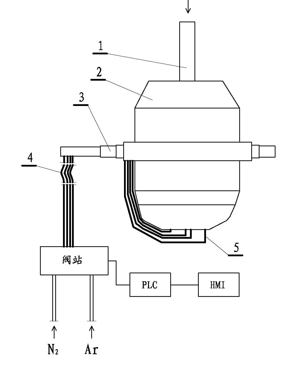
[0031] A method for automatic bottom blowing control of a converter, the hardware system used in the method, such as figure 1 shown. The hardware system used in the method described in this embodiment includes: a converter 2 with re-blowing function, an oxygen pipe 1 is arranged on the upper part of the converter, and oxygen is blown into the furnace. Ventilation bricks are arranged at the bottom of the converter. The branch pipeline 5 connected to the air brick is connected to the valve station through the rotary joint 3 of the converter trunnion and the metal hose 4 . The valve station for supplying argon and nitrogen is actually a device for controlling the switching and flow of argon and nitrogen, and consists of a series of pressure regulating valves, gas bags, branch pipe flow regulating valves, etc. PLC is an electronic control system that can control the valve station. PLC has a man-machine exchange interface HMI, and the controller can control the smelting process t...
Embodiment 2
[0047] This embodiment is an improvement of the first embodiment, and it is a refinement of the bottom blowing model of the first embodiment. The bottom blowing model described in the present embodiment comprises:
[0048] According to the requirements of the steel type on the nitrogen content in the finished product, it is divided into the following three bottom blowing control methods:
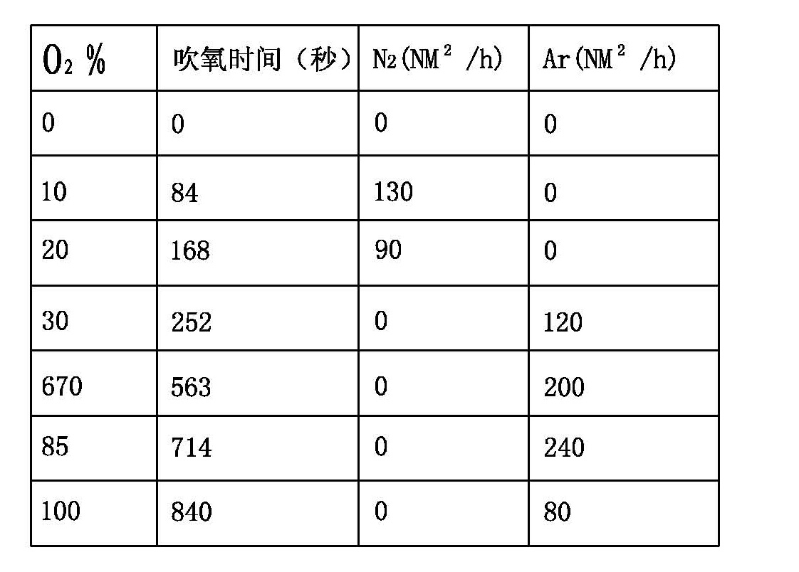
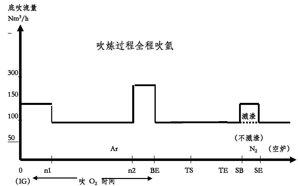
[0049] a. For steel types with N ≤ 40PPM, argon is blown throughout the bottom blowing of the converter during the blowing process. image 3 It is a schematic diagram of the blowing process of blowing argon throughout. The vertical axis represents the gas flow rate of bottom blowing, and the straight horizontal line is only for illustration, and there are usually some fluctuations in the actual smelting process, especially in the process of oxygen blowing. exist figure 2 This change can be seen in the table of .
[0050] b. For steel grades with 40 Figure 4 Schematic diagram of blowing ...
Embodiment 3
[0061] This embodiment is an improvement of Embodiment 2, which relates to the refinement of nine bottom blowing models displayed on the HMI. The nine bottom blowing models described in this embodiment are represented by 1-9 Arabic numerals respectively, and the nine Arabic numerals are displayed on the HMI in the form of a bottom blowing model matrix, and steel is marked on the upper and left sides of the bottom blowing model matrix respectively. The carbon content and nitrogen content of the species, such as Figure 6 shown.
[0062] The nine bottom blowing models in this embodiment are displayed on the HMI, which is a concise display, and the controller can easily select the required model from the bottom blowing model matrix. When selecting, you only need to observe the nitrogen content on the far left of the bottom blowing model matrix and the carbon content in the upper part of the bottom blowing model matrix, and then look for the intersection point of the two, which i...
PUM
 Abstract
Description
Claims
Application Information
 - R&D
- Intellectual Property
- Life Sciences
- Materials
- Tech Scout
- Unparalleled Data Quality
- Higher Quality Content
- 60% Fewer Hallucinations
Browse by: Latest US Patents, China's latest patents, Technical Efficacy Thesaurus, Application Domain, Technology Topic, Popular Technical Reports.
© 2025 PatSnap. All rights reserved.Legal|Privacy policy|Modern Slavery Act Transparency Statement|Sitemap|About US| Contact US: help@patsnap.com


