Total reflection fluorescence observation device
a fluorescence observation and fluorescence technology, applied in the direction of luminescent dosimeters, optical radiation measurement, instruments, etc., can solve the problems of inconvenient and complicated optical adjustment (for strictly aoi) and other problems, to achieve the effect of improving reliability, improving operability and keeping evanescent light intensity high
- Summary
- Abstract
- Description
- Claims
- Application Information
AI Technical Summary
Benefits of technology
Problems solved by technology
Method used
Image

Examples
first embodiment
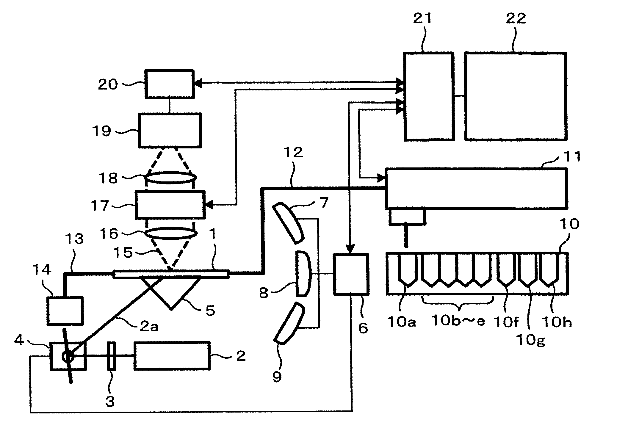
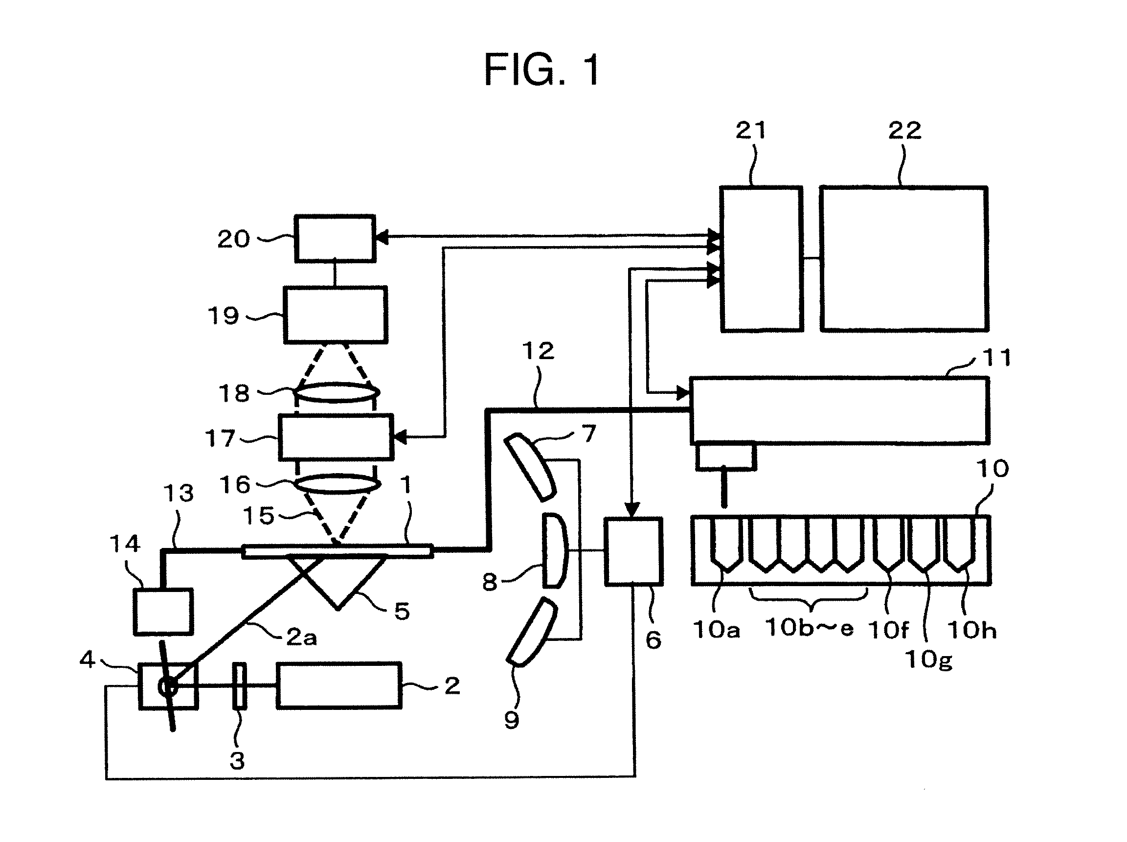
[0045]FIG. 1 is a diagram of a DNA base sequence analysis device having an angle adjusting function in this embodiment. The device has a configuration like an erecting microscope. The device measures, in fluorescence detection, fluorescent molecules captured on a substrate 1. It is also possible to configure the device as an inverted microscope. When this operation is based on a unimolecular fluorescence detecting method, measurement is performed in an environment like a clean room via an HEPA filter.
[0046]A series of reaction is performed on reaction substrate 1. The substrate 1 is made of a transparent material. As the material, for example, synthetic quartz can be used. Plural primers are fixed to the substrate. For example, a 5′ terminal end of the primers is biotinylated and a substrate surface is avidinated. The primers are fixed to the surface of the substrate 1 using biotin-avidin binding. The primers may be arranged on the substrate at random. However, it is desirable to re...
second embodiment
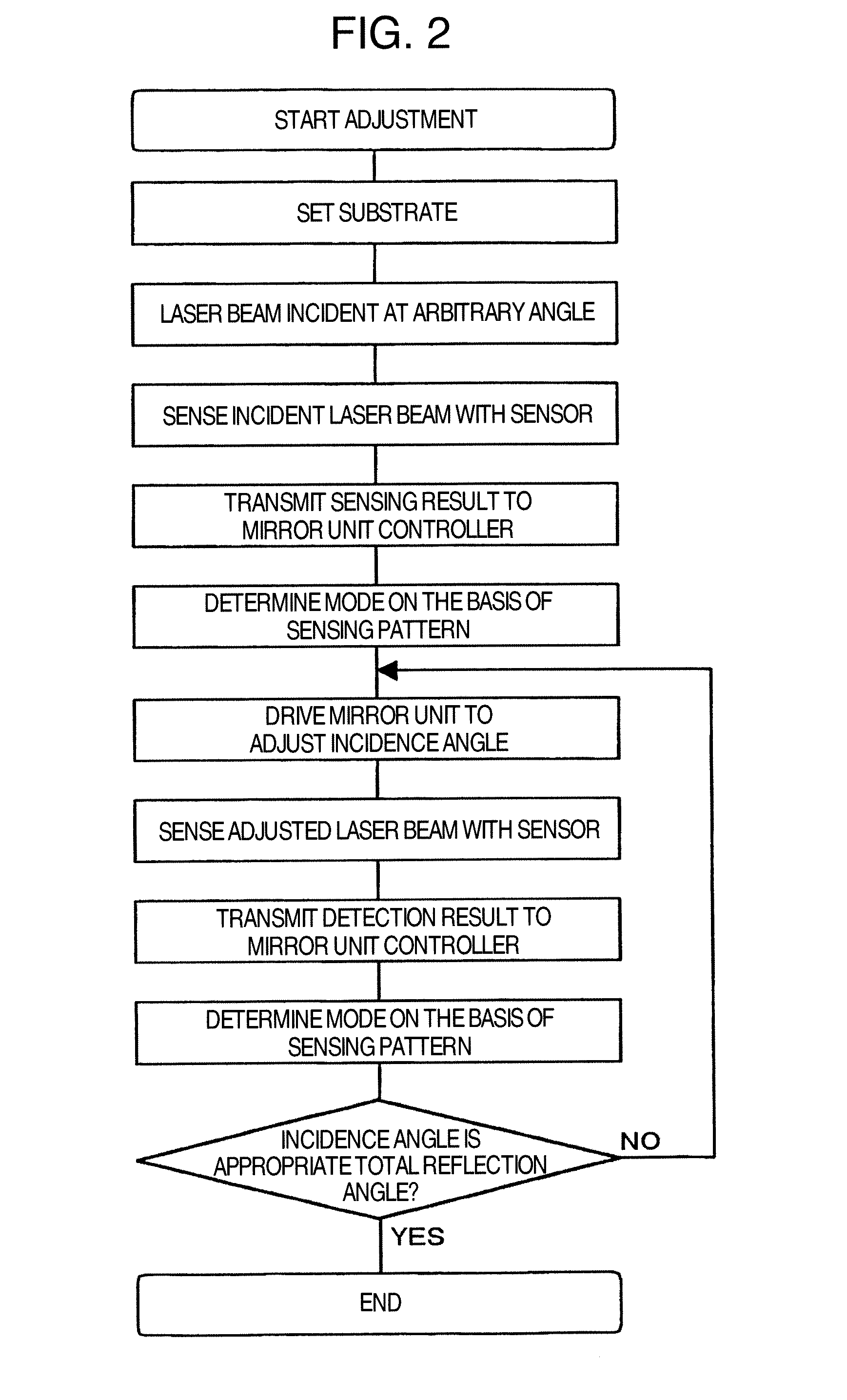
[0072]In the first embodiment, transmitted light, surface diffusing light, a reflected light are sensed by the three optical sensors. However, it is also possible to sense the three lights with one optical sensor 23. Specifically, the three kinds of light are respectively led to sectioned three areas of the optical sensor 23 directly or by an optical element such as a mirror. A sensing result of the optical sensor 23 is sent to the mirror unit controller 6. The mirror unit controller 6 drives the mirror unit 4 on the basis of the information. As in the first embodiment, the mirror unit controller 6 includes five modes. The mirror unit 4 automatically performs adjustment according to rules determined for each of the modes so that an angle of incidence is a total reflection angle. Alternatively, as in the first embodiment, the mirror unit controller 6 includes five modes and determines a mode according to a sensing pattern of the optical sensor 23. The mirror unit controller 6 issues ...
third embodiment
[0073]In the first embodiment, the three lights of transmitted light, surface diffusing light, and reflected light are sensed. However, lights to be sensed can also be two lights of transmitted light and surface diffusing light. As in the first embodiment, the laser beam 2a is shone at an arbitrary angle of incidence on a measurement area on the surface of the substrate 1. The angle is, for example, 45 degrees. The optical sensors 7 and 8 for sensing transmitted light and surface diffusing light are set in the device. Sensing results of these sensors are sent to the mirror unit controller 6. The mirror unit controller 6 drives the mirror unit 4 on the basis of the information. The driving is performed by means same as that in the first embodiment. The mirror unit controller 6 includes five modes shown in a table below and determines a mode according to a sensing pattern of the optical sensors 7 and 8. The mirror unit 4 automatically performs adjustment according to rules determined ...
PUM
 Abstract
Description
Claims
Application Information
 - R&D Engineer
- R&D Manager
- IP Professional
- Industry Leading Data Capabilities
- Powerful AI technology
- Patent DNA Extraction
Browse by: Latest US Patents, China's latest patents, Technical Efficacy Thesaurus, Application Domain, Technology Topic.
© 2024 PatSnap. All rights reserved.Legal|Privacy policy|Modern Slavery Act Transparency Statement|Sitemap