Bumper system

a bumper and bumper technology, applied in the direction of bumpers, vehicle safety arrangments, transportation and packaging, etc., to achieve the effect of preventing damage to the support structure of the vehicle and smallest possible bending momen

Active Publication Date: 2011-05-26
BENTELER AUTOMOBILTECHNIK GMBH
View PDF5 Cites 25 Cited by
  • Summary
  • Abstract
  • Description
  • Claims
  • Application Information

AI Technical Summary

Benefits of technology

[0009]Stiffness of the crossbeam is an important factor for the deformation behavior in the event of a crash at high speed. By removing the inner wall from the area of the attachment zones, the crossbeam is able to more easily collapse or crumple in the attachment zones, resulting in greater ductility of the crash behavior in a collision at lower speed. Recessing or shortening the inner wall to leave a gap in the attachment zone also reduces the force level in the event of a crash. The bumper system thus exhibits an optimal force level and optimal absorption capability. Of course, the inner wall may also be formed with additional gaps over its entire length for decreasing the overall weight for example.
[0017]According to another advantageous feature of the present invention, the crash boxes may be connected to the crossbeam by welding or bolting or a combination thereof. This further optimizes crash behavior of crossbeam and crash box. For example, the tongue may be welded about its circumference to the crossbeam, so that the stiffness and crumpling behavior of tongue and crossbeam can further be optimized.

Problems solved by technology

Reconciliation of these seemingly contradictory requirements poses a problem heretofore to optimize bumper designs when considering the acceleration encountered in the event of a crash in relation to the deformation path.

Method used


Image

  • Bumper system
  • Bumper system
  • Bumper system

Examples


Embodiment Construction

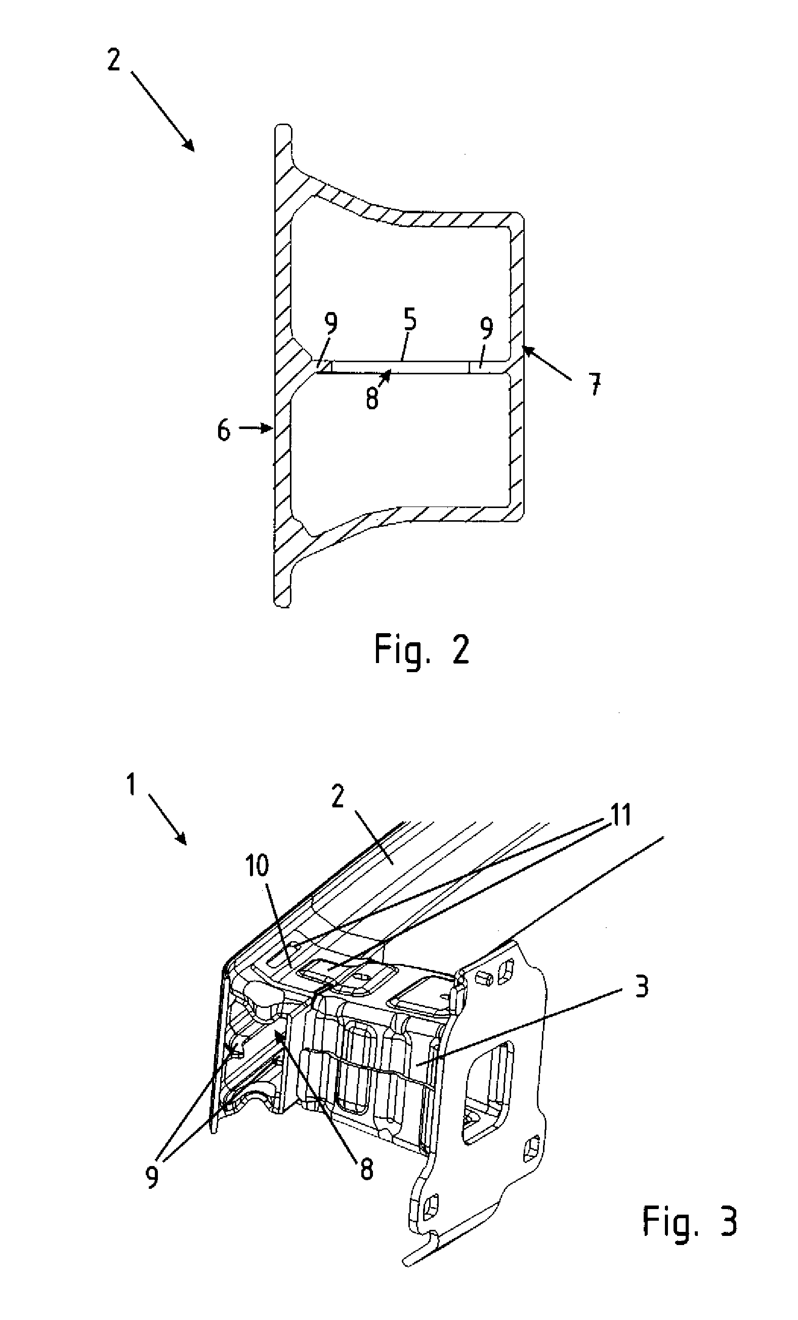
[0024]Throughout all the figures, same or corresponding elements may generally be indicated by same reference numerals. These depicted embodiments are to be understood as illustrative of the invention and not as limiting in any way. It should also be understood that the figures are not necessarily to scale and that the embodiments are sometimes illustrated by graphic symbols, phantom lines, diagrammatic representations and fragmentary views. In certain instances, details which are not necessary for an understanding of the present invention or which render other details difficult to perceive may have been omitted.

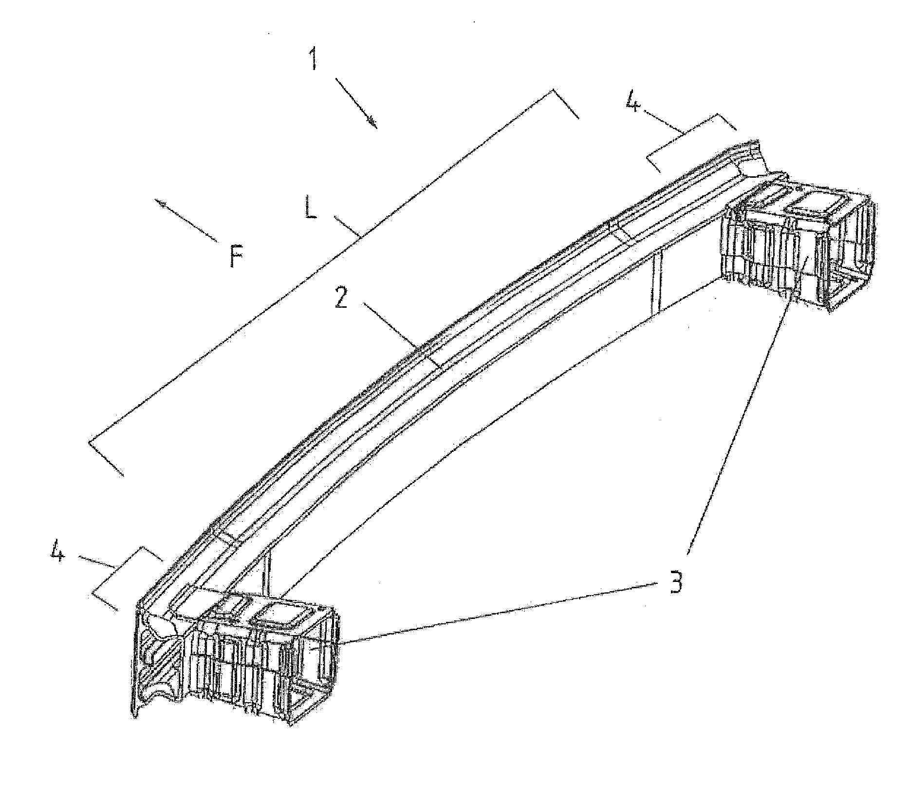
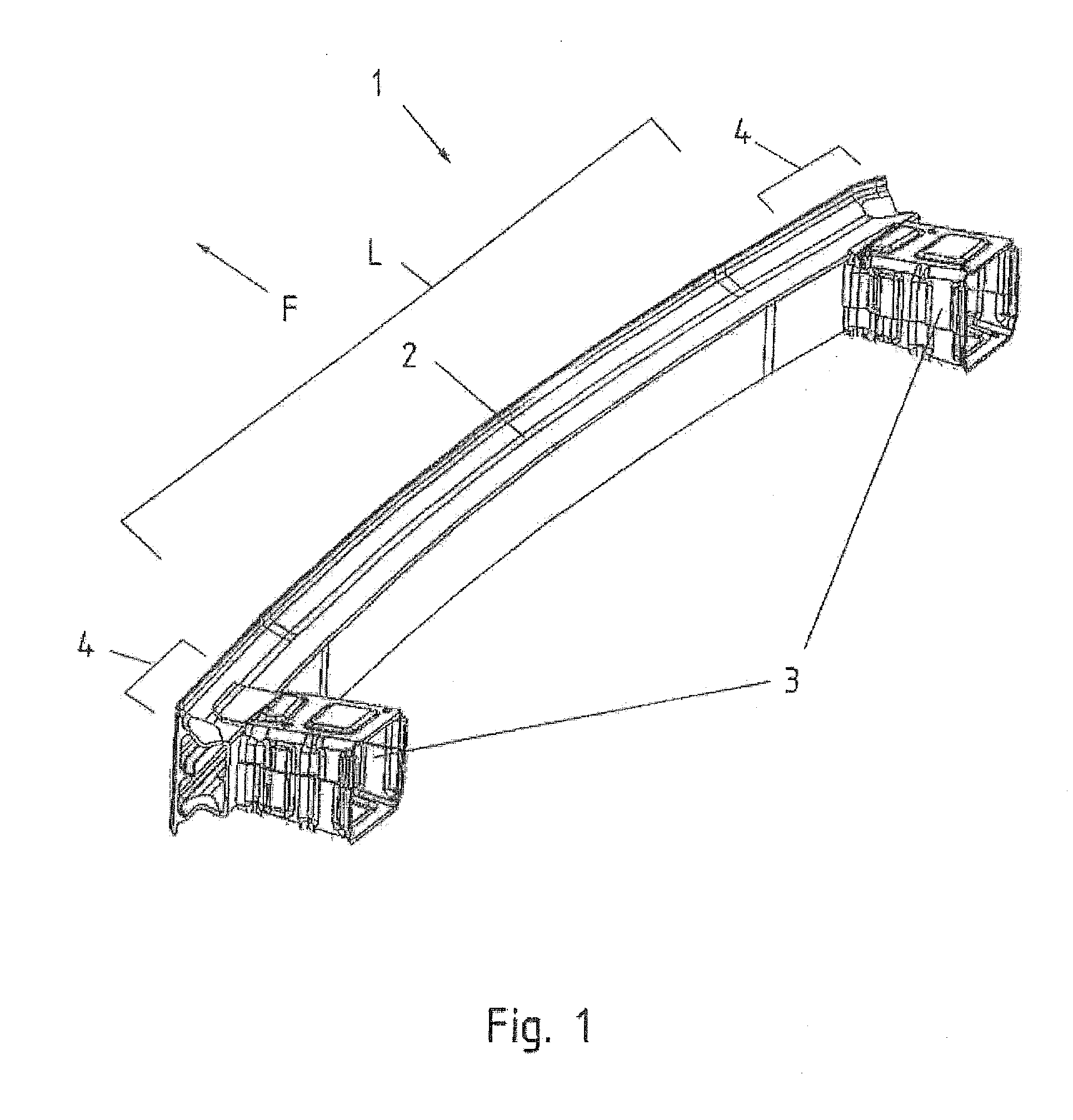
[0025]Turning now to the drawing, and in particular to FIG. 1, there is shown a top, rear and side perspective view of a bumper system according to the present invention, generally designated by reference numeral 1 and including a crossbeam 2 and two crash boxes 3 which are coupled to the crossbeam 2 in attachment zones 4 and secured to unillustrated side rails of a motor ve...


PUM


Abstract

A bumper system includes a crossbeam having ends constructed to form attachment zones, and two crash boxes which are secured to side rails of a motor vehicle and coupled to the attachment zones, respectively. The crossbeam has a front wall, a rear wall, and an inner wall which extends between the front and rear walls along a major length of the crossbeam. The inner wall is hereby recessed to leave a gap in the area of the attachment zones.

Description

CROSS-REFERENCES TO RELATED APPLICATIONS[0001]This application claims the priority of German Patent Application, Serial No. 10 2009 053 861.5-21, filed Nov. 20, 2009, pursuant to 35 U.S.C. 119(a)-(d), the content of which is incorporated herein by reference in its entirety as if fully set forth herein.BACKGROUND OF THE INVENTION[0002]The present invention relates to a bumper system for a motor vehicle.[0003]The following discussion of related art is provided to assist the reader in understanding the advantages of the invention, and is not to be construed as an admission that this related art is prior art to this invention.[0004]Bumpers are typically installed across the front and rear of motor vehicles to absorb impact energy in the event of a collision to substantially prevent damage to the support structure of the vehicle. The bumper system normally includes a shock-absorbing component, like a crash box, to convert the impact energy into deformation work, and a crossbeam to introd...

Claims


Application Information

Patent Timeline
Patent Type & Authority Applications(United States)
IPC IPC(8): B60R19/34
CPCB60R19/18B60R2019/1826B60R2019/182B60R19/34
Inventor HANDING, CHRISTIANTATARINOV, KONSTANTINROLL, MICHAELGREWE, JOCHEM
Owner BENTELER AUTOMOBILTECHNIK GMBH
Why Eureka
Try Eureka