Milling Tool, Particularly Face-Milling Cutter

a cutting tool and face-milling technology, which is applied in the field of face-milling cutting tools, can solve the problems of not being able to mount well, and not being able to meet the requirements of high-speed machining. , to achieve the effect of reliable mounting of the cutting body

Active Publication Date: 2011-05-26
AUDI AG
View PDF9 Cites 0 Cited by
  • Summary
  • Abstract
  • Description
  • Claims
  • Application Information

AI Technical Summary

Benefits of technology

[0022]In one alternative embodiment, the clamping element can have clamping support edges on both sides opposite the fastening element (without support by way of a rocker crosspiece). The cutting bodies each have support shoulders on both

Problems solved by technology

There are no measures for controlled chip removal with separation of the chip space from the surface to be machined, so that during metal cutting the respective chip can come into unimpeded contact with the workpiece surface to be machined and may in this way potentially damage it.
Moreover, here the cutting bodies are held solely by frictional locking against radial centrifugal force so that this arrangement is not suitable for high-speed machining with high rotational speeds and high centrifugal forces.
Furthermore, a similar milling tool is known (FR 2 422 468) in which the chip space does not have any separation and thus any controlled chip guidance function toward the workpiece surface to be machined so that here damage of the workpiece surface to be machined by the chip is also possible during metal cutting.
Here as well, the cutting bodies are only squeezed with respect to the radial forces so that

Method used


Image

  • Milling Tool, Particularly Face-Milling Cutter
  • Milling Tool, Particularly Face-Milling Cutter
  • Milling Tool, Particularly Face-Milling Cutter

Examples


Embodiment Construction

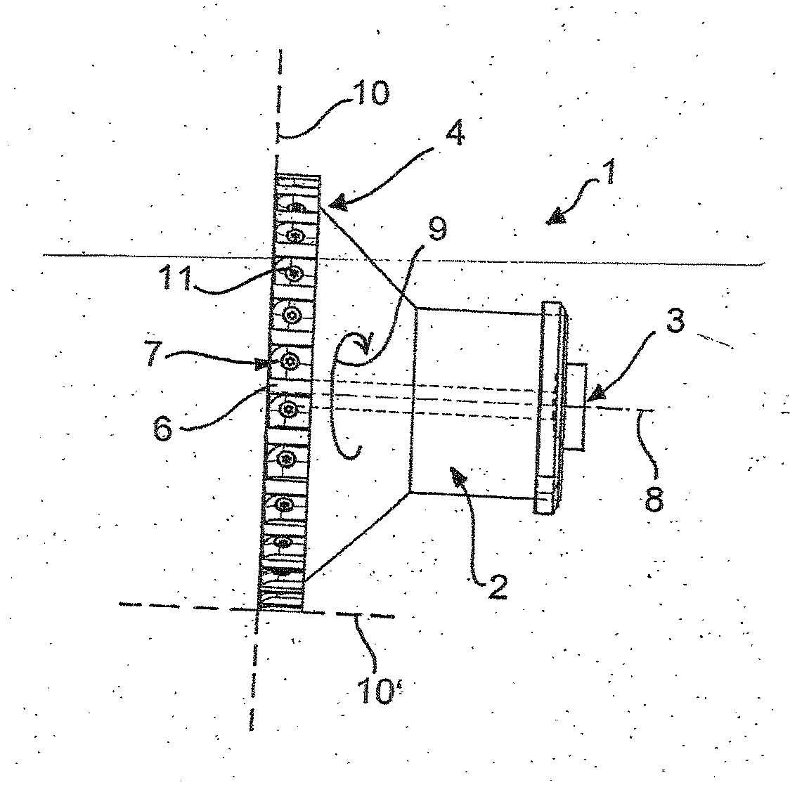
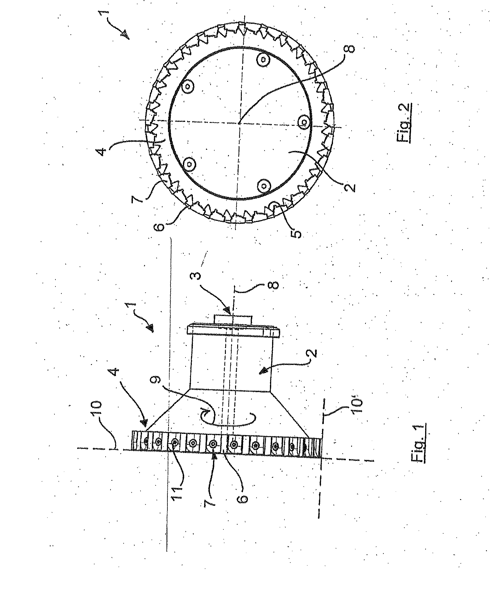
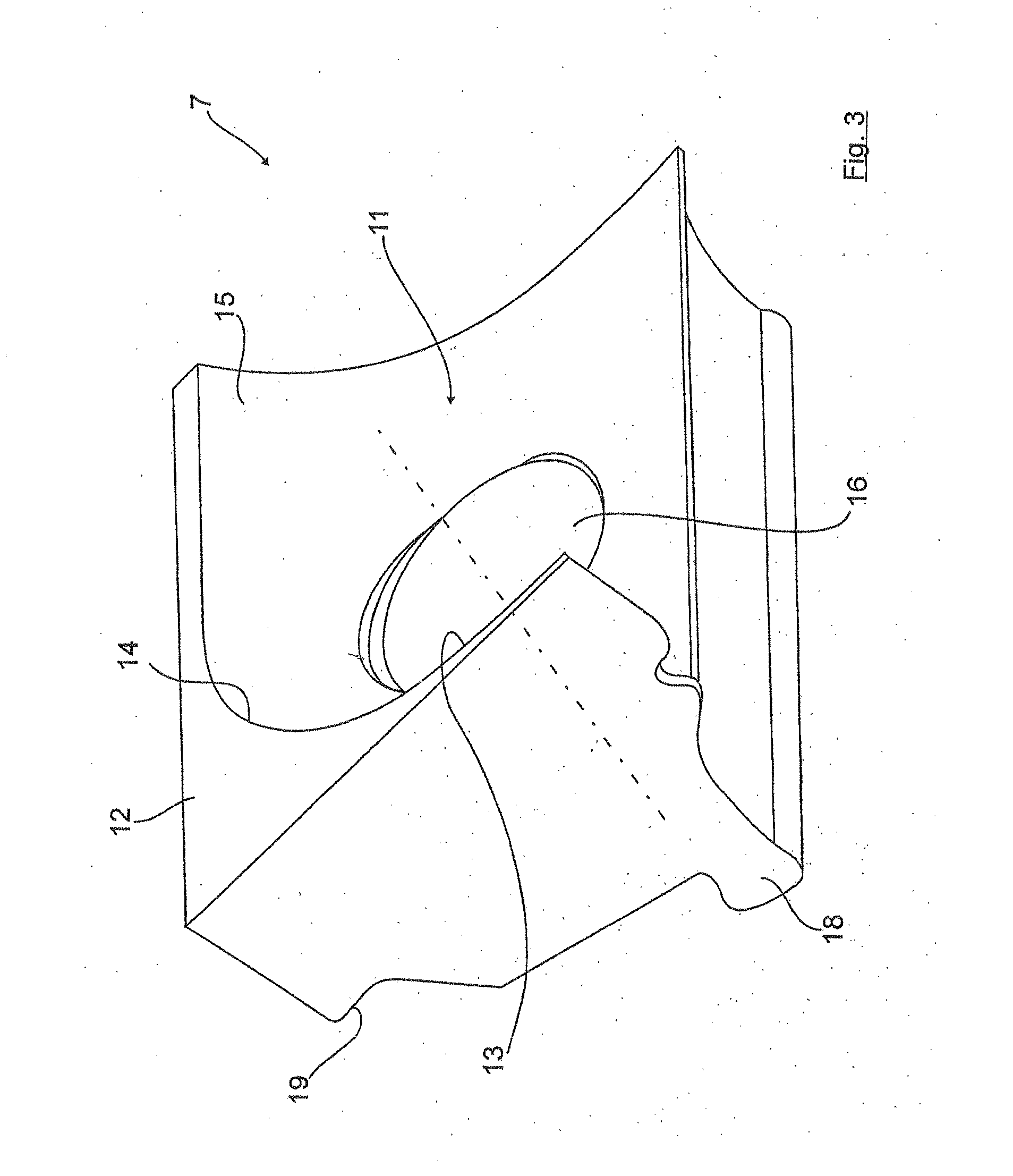
[0028]FIGS. 1 and 2 show a face cutter 1 in a side view and a front top view which has a rotationally symmetrical tool base body 2 which widens from a cylindrical region in a conical shape as far as the end-side circular ring 4. In this circular ring 4 on the periphery in succession a plurality of identical pocket-like recesses 5 are made into which on the one hand cutting bodies 6 and clamping elements 7 bordering as clamping jaws are inserted which are further explained in detail using the enlarged depictions of FIGS. 3 to 5.

[0029]The tool base body 2 is driven around the axis 8 of rotation according to the rotary arrow 9. For metal-cutting facing of a workpiece surface 10 perpendicular to the axis 8 of rotation (or optionally for a workpiece surface 10′ axially parallel to the axis 8 of rotation), the cutting bodies 6 project radially and / or axially on the circular ring 4 of the workpiece base body 2 with their cutting edges.

[0030]As is apparent from FIG. 1, the chips which have ...


PUM

PropertyMeasurementUnit
Forceaaaaaaaaaa

Abstract

The invention relates to a milling tool, particularly a face-milling cutter, with a rotationally symmetrical tool base body which can be driven in rotation and in which at least one pocket-like recess is made on the periphery, with a cutting body which is inserted in the recess, which projects radially and/or axially on the tool base body and which is held by at least one clamping element, on the outer periphery of the milling tool at least one chip guide chamber being made with chip deflecting surfaces for controlled chip removal away from the workpiece surface to be machined. According to the invention, the chip guide chamber is assigned at least one chip guide web which separates the chip guide chamber from the surface of the workpiece.

Description

[0001]This invention relates to a milling tool, particularly a face-milling cutter.BACKGROUND OF THE INVENTION[0002]A generic, known milling tool (DE 101 44 514 A1) consists of a cylindrical tool base body which can be driven in rotation, in which pocket-like recesses are made on the periphery. Cutting bodies are inserted into these recesses, project radially and / or axially on the tool base body, and are held by respectively assigned clamping elements.[0003]In the direction of rotation in front of the cutting bodies, the clamping elements are arranged here such that they lie radially offset to the inside in the fully mounted state relative to the peripheral surface of the tool base body and the cutting edge of the pertinent cutting bodies, by which a chip space for accommodating chips is formed. There are no measures for controlled chip removal with separation of the chip space from the surface to be machined, so that during metal cutting the respective chip can come into unimpeded ...

Claims


Application Information

Patent Timeline
IPC IPC(8): B23C5/06B23C5/22B23B27/22
CPCB23C5/06B23C5/22B23C2210/16Y10T407/11B23C5/20Y10T407/24Y10T407/192B23C2230/04
Inventor KOPTON, PETER
Owner AUDI AG
Why Eureka
Try Eureka