
Limiting radial preloads in securing an orthopedic fastener

a technology of limiting radial preload and securing an orthopedic fastener, which is applied in the field of orthopaedic fasteners, can solve the problems of micro-motion between the fastener and the bone, high stress conditions at the remaining contact area, and potential damage to the hole surrounding the bone hole, so as to avoid bone damage and be simple to manufactur

Active Publication Date: 2011-05-26
IMEX VETERINARY LLC
View PDF22 Cites 2 Cited by
  • Summary
  • Abstract
  • Description
  • Claims
  • Application Information

AI Technical Summary

Benefits of technology

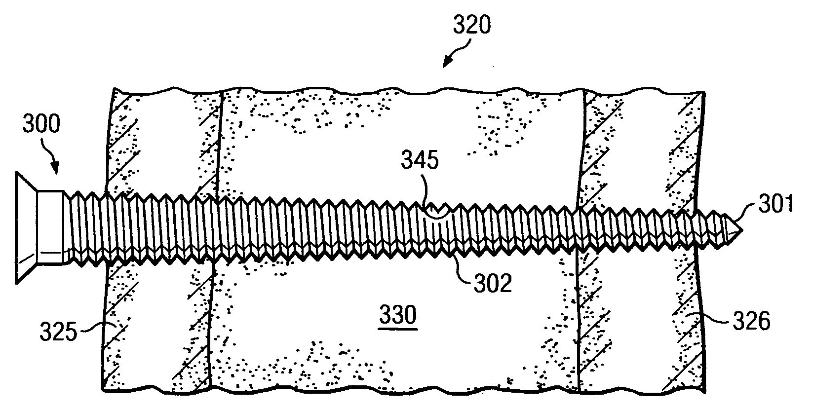
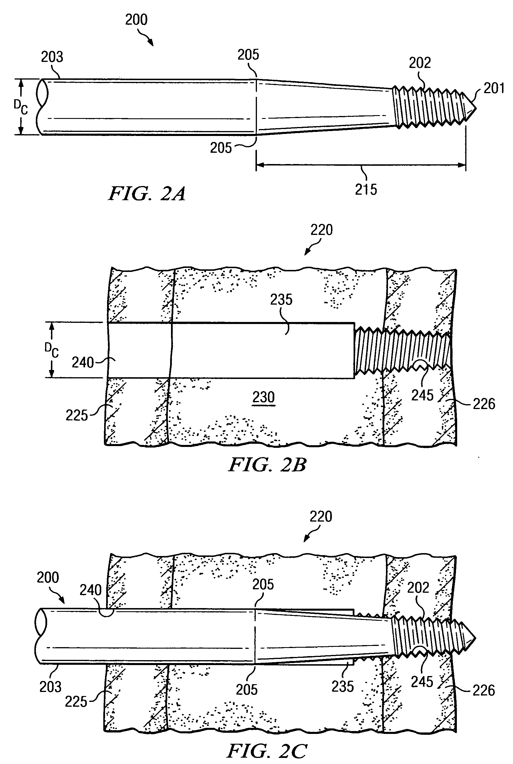
[0016]It is therefore a technical advantage of the invention to provide an orthopedic fastener that, once secured in a specimen of bone, is less prone to loosening. Assuming that the fastener of the present invention is secured into a bone specimen for which the fastener is rated, the tapered diameter portion on the shank will reside in entry portion in the near cortex when the threaded portion on the fastener is secured into the far cortex.

Problems solved by technology

A common complication of fracture repair, external fixation (or other orthopedic procedures in which fasteners are inserted into bone) is loosening of the fastener over time at the fastener / bone interface.
This micro-displacement temporarily deforms the shape and size of the bone hole into which the fastener is secured, resulting in loss of circumferential contact between the fastener and the bone, which in turn leads to higher stress conditions at the remaining areas of contact.
However, while the higher elasticity of the metal fastener allows the fastener to resume its original shape and relative position within the bone hole after loading, the lower elasticity of the bone surrounding the bone hole leaves the hole potentially damaged after loading.
As a result, there is a loss of contact between fastener and the bone during and potentially after loading, resulting in micro-motion between fastener and bone, manifesting itself over time and repetitive loading as loosening of the fastener.
However, as taught by Biliouris et al., the bone material's comparatively low elasticity limits the amount of radial preload that can be absorbed by the bone material without causing cracking of the bone material around the oversized portion of the fastener.
Biliouris et al. observe that a fastener diameter more than about 0.2 mm greater than the receiving bone hole is prone to cause micro-cracking in surrounding cortical bone material.
As a result, no structure to measure or limit radial preload is disclosed.
These disclosures provide no guidance, however, on imparting limited or controlled amounts of radial preload into the bone surrounding the fastener.
Likewise U.S. Pat. No. 6.565,573 (Ferrante et al.) and U.S. Pat. No. 6,375,657 (Doubler et al.) disclose bone fasteners with generally tapered threads, but the disclosures of these patents provide no guidance on imparting limited or controlled amounts of radial preload into the bone surrounding the fastener.
As with other prior art discussed above, however, Navarro et al. provide no guidance on imparting limited or controlled amounts of radial preload into the bone surrounding the fastener.

Method used


Image

  • Limiting radial preloads in securing an orthopedic fastener
  • Limiting radial preloads in securing an orthopedic fastener
  • Limiting radial preloads in securing an orthopedic fastener

Examples


Embodiment Construction

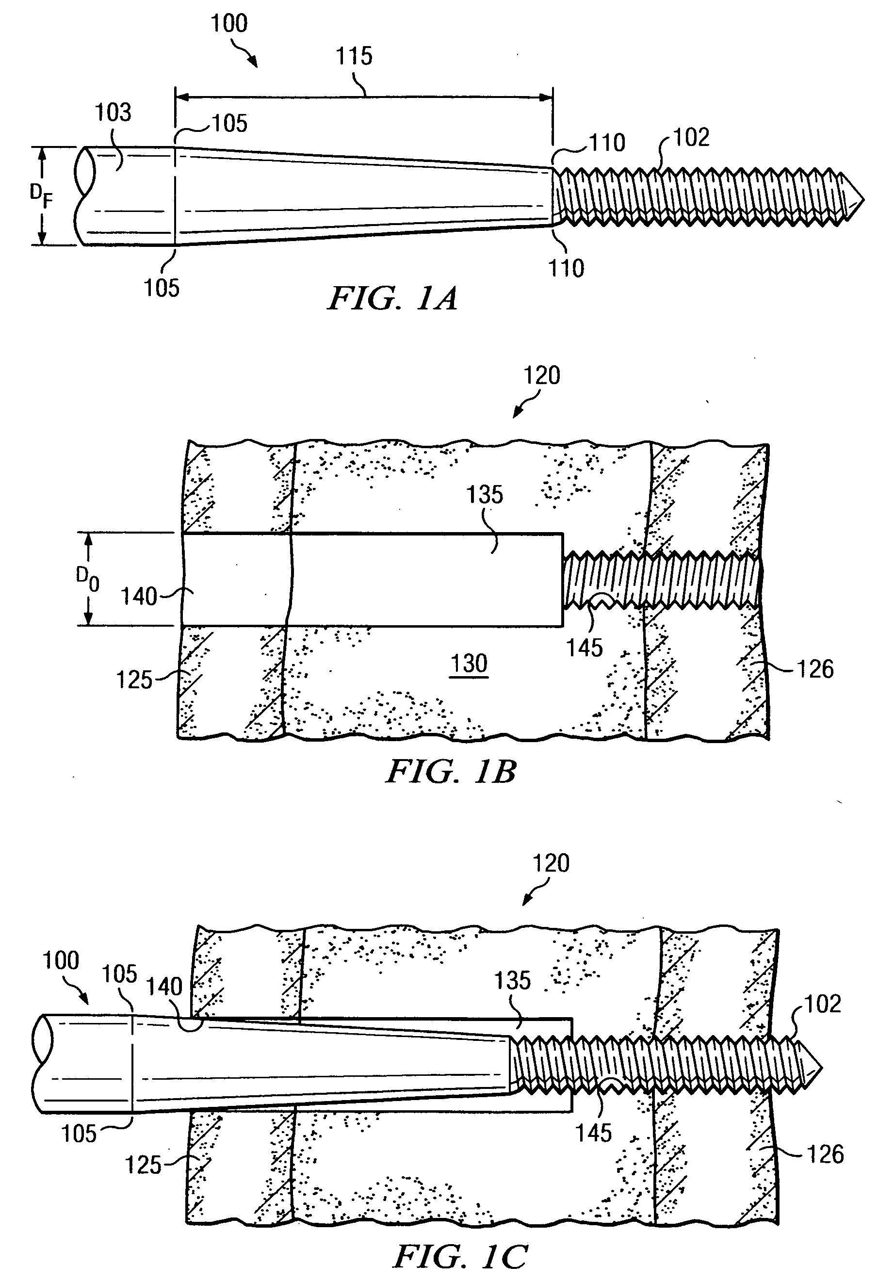
[0025]FIGS. 1A, 1B and 1C should be viewed together, and depict a first aspect of the present disclosure, in which an orthopedic fastener 100 is configured to limit and / or control radial preloads exerted in near cortex 125 as fastener 100 is operably secured into bone specimen 120. FIG. 1A illustrates a segment of fastener 100 in isolation. FIG. 1B illustrates bone specimen 120 with opening 135 prepared to receive fastener 100. FIG. 1C illustrates fastener 100 received into opening 135 and operably secured into bone specimen 120.

[0026]Referring first to FIG. 1A, fastener 100 provides threaded portion 102 on one end. Fastener 100 further provides unthreaded cylindrical portion 103 with a pre-selected constant diameter DF. Threaded portion 102 and cylindrical portion 103 are separated by a smooth tapered portion 115. Tapered portion 115 is bounded by reference points 105 and 110, as illustrated on FIG. 1A. Reference point 105 is the point at which cylindrical portion 103 ends and tape...


PUM


Abstract

An orthopedic fastener rated to be received into a corresponding bone specimen. The corresponding bone specimen has (1) an overall outer thickness from near cortex to far cortex in a predetermined rated range of outer bone thicknesses, and (2) a predetermined bone hole preparation including an entry portion in the near cortex. The entry portion has a predetermined minimum entry diameter. The fastener provides a tapered portion. When the fastener is operably secured into the far cortex of a bone thickness for which it is rated to be received, the tapered portion of the fastener contacts the entry portion in the near cortex so as to impart no more than about 0.2 mm of radial preload into the bone surrounding the entry portion.

Description

FIELD OF THE INVENTION[0001]This invention relates generally to orthopedic fasteners, and more specifically, in preferred embodiments, to orthopedic fasteners configured to exert, when secured into cortical bone, no more than a predetermined amount of radial preload in the cortical bone material surrounding the fastener's regions of contact with the bone.BACKGROUND OF THE INVENTION[0002]A common complication of fracture repair, external fixation (or other orthopedic procedures in which fasteners are inserted into bone) is loosening of the fastener over time at the fastener / bone interface. In their article “The Effect of Radial Preload on the Implant / Bone Interface: A Cadaveric Study”, Biliouris et al. suggest several reasons for this loosening, including micro-movement of the bone tissue as axial or bending loads are exerted on the fastener during normal use of the fastened bone by the patient after surgery. As described in some detail in the above-referenced article (hereafter refe...

Claims


Application Information

Patent Timeline
IPC IPC(8): A61B17/86
CPCA61B17/8625A61B17/60
Inventor GRIFFIN, T. HALL
Owner IMEX VETERINARY LLC
Learn More