Method and apparatus for reducing collision injury/damage of vehicles

a collision injury and vehicle technology, applied in the direction of pedestrian/occupant safety arrangement, brakes, instruments, etc., can solve the problems of large error in collision speed v calculated using such a ttc, difficulty in changing a preset threshold speed, and low threshold determination accuracy

Active Publication Date: 2011-05-26
DENSO CORP
View PDF22 Cites 99 Cited by
  • Summary
  • Abstract
  • Description
  • Claims
  • Application Information

AI Technical Summary

Benefits of technology

[0010]In order to solve the problem set forth above, an embodiment provides a collision injury / damage reduction apparatus which is able to highly accurately determine, immediately before the collision between an object and the vehicle equipped with the unit, regarding whether or not protection devices should be actuated.
[0012]When a TTC calculated by the time calculating means is equal to or less than a preset first threshold time, automatic braking means carries out automatic intervention braking of the vehicle. When the TTC is equal to or less than a second threshold time (which is preset to a value smaller than the first threshold time) and meets predetermined conditions of actuation, protective actuating means actuates protection devices (devices installed in the vehicle in order to reduce injuries and damage caused by the collision between the vehicle and an object).
[0016]Thus, according to the collision injury / damage reduction apparatus of the embodiment, change of the relative speed on or after the time point when the TTC has become equal to the second threshold time is reflected in the threshold determination. Therefore, the results of the threshold determination match the actual behavior (travel status) of the vehicle. Further, a highly accurate determination can be made, immediately before the possible collision between an object and the vehicle, regarding whether or not the protection devices should be actuated. In this way, erroneous actuation of the protection devices is reduced.
[0020]In this way, the collision speed V is calculated from the Formula (2) without using a TTC which may include a large error. Accordingly, comparing with the case where the Formula (1) is used, the reliability of the collision speed V is enhanced, and further, the accuracy of the determination made by the protective actuating means is more enhanced.
[0023]In the latter case, the deceleration (which is an actual measurement value) actually caused to the vehicle by the automatic intervention braking is reflected in the collision speed V. Accordingly, when the actual measurement value of the deceleration is deviated from a requested value due to the road surface conditions, for example, a collision speed that matches the actual travel status can be calculated. Thus, compared to the former case, the reliability of the collision speed V is enhanced, and further, the accuracy of the determination made by the protective actuating means is more enhanced.
[0027]Specifically, the protection devices operable reversibly can dispense with the reinstallation of new protection devices, should the protection devices be actuated when unwanted. Thus, cost is advantageously reduced.

Problems solved by technology

Meanwhile, it is difficult to change a preset threshold speed, for the purpose of reducing erroneous actuation of the protection devices.
As a result, the accuracy of a threshold determination tends to become comparatively low.
Accordingly, the collision speed V calculated using such a TTC may include a large error in the case where the relative speed has changed significantly before an actual collision.

Method used


Image

  • Method and apparatus for reducing collision injury/damage of vehicles
  • Method and apparatus for reducing collision injury/damage of vehicles
  • Method and apparatus for reducing collision injury/damage of vehicles

Examples


Embodiment Construction

[0037]With reference to the accompanying drawings, hereinafter are described an embodiment and modifications of the present invention.

[0038]With reference to FIGS. 1-5, an embodiment of a method and apparatus for reducing collision injury / damage of vehicles, which is according to the present invention, will now be described.

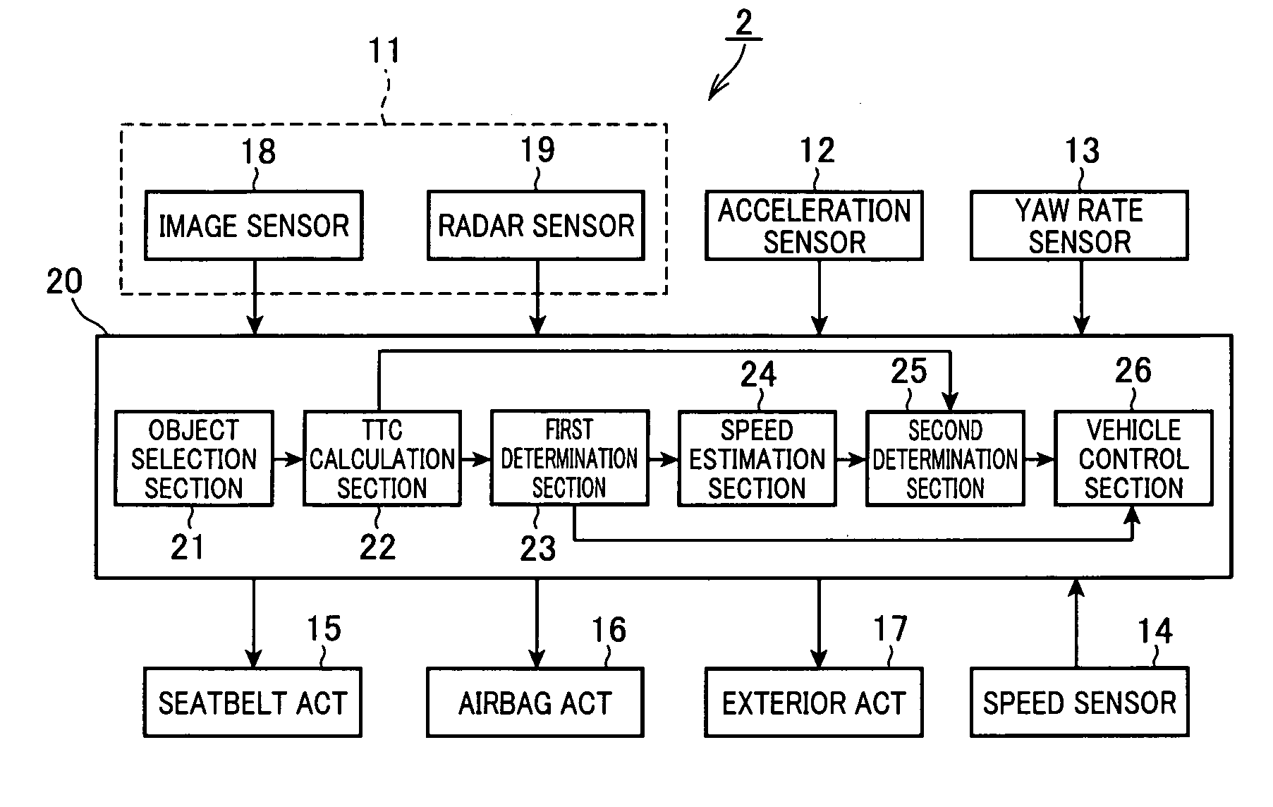
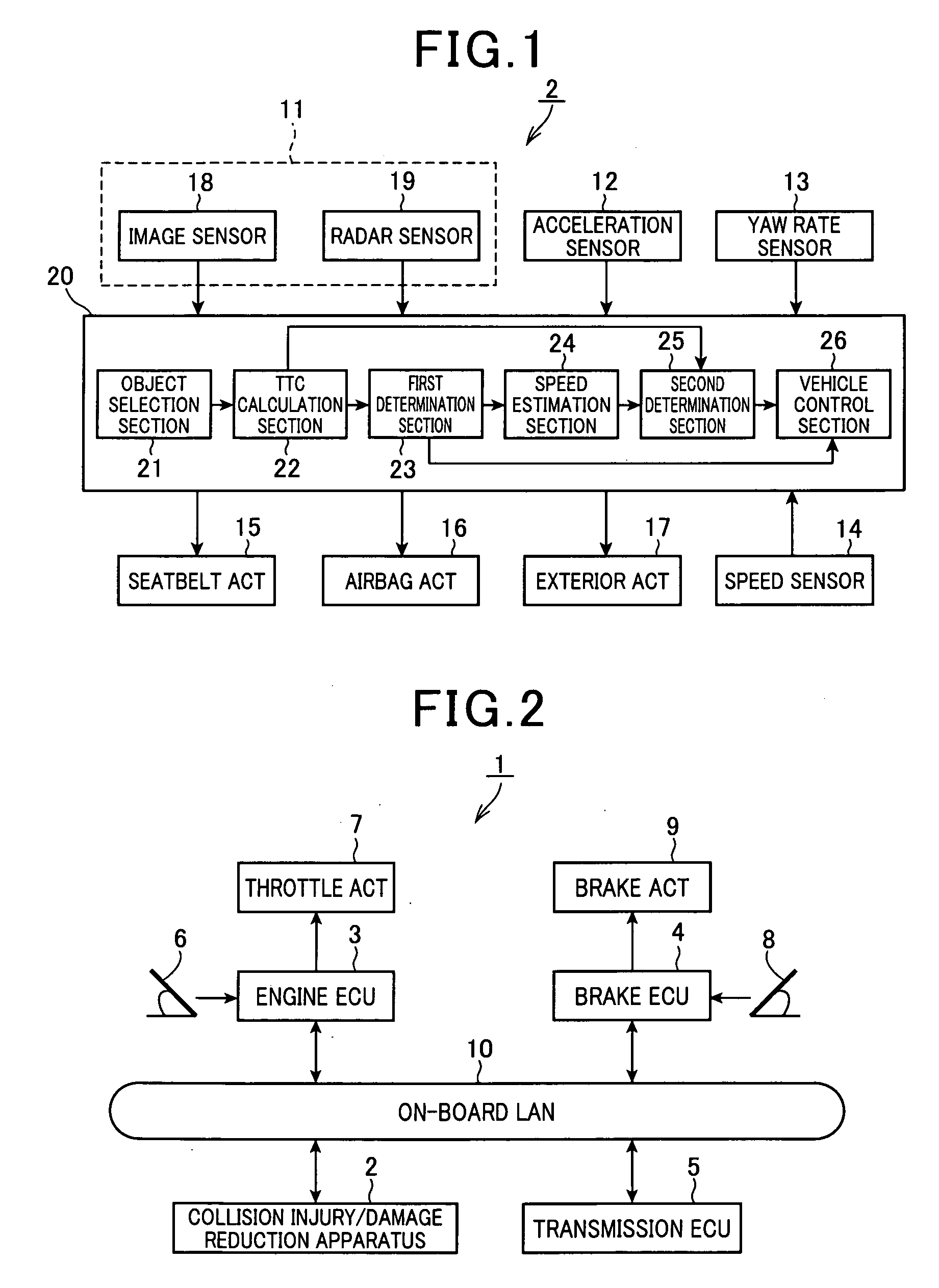
[0039]FIG. 1 is a block diagram illustrating a configuration of a collision injury / damage reduction apparatus 2 according to the embodiment, in which the apparatus 2 is carried out as the apparatus according to the present invention. FIG. 2 is a block diagram illustrating a general configuration of an on-board system 1 provided with the collision injury / damage reduction apparatus 2.

[0040]As shown in FIG. 2, besides the collision injury / damage reduction apparatus 2, the on-board system 1 includes an engine ECU 3, a brake ECU 4 and a transmission ECU 5. The engine ECU 3 serves as an electronic control unit (control system ECU) associated with cruise control of a ve...


PUM


Abstract

An on-vehicle apparatus is provided to reduce damage from collisions. In the apparatus, an object located in a field in a travel direction of a vehicle is detected and a time to collision (TTC) is detected. A controller performs automatic intervention braking in the vehicle when it determined that the time to collision is equal to or shorter than a first threshold time. Further, when it determined that the time to collision is equal to or shorter than a second threshold time shorter than the first threshold time and meets a preset actuation condition, a protection controller makes a protection device active for vehicle protection. A collision speed is also estimated based on an deceleration of the vehicle caused by the automatic intervention braking. The preset actuation condition is a condition that the estimated collision speed is equal to or higher than a preset threshold speeds.

Description

CROSS-REFERENCE TO RELATED APPLICATION[0001]This application is based on and claims the benefit of priority from earlier Japanese Patent Application No. 2009-264843 filed Nov. 20, 2009, the description of which is incorporated herein by reference.BACKGROUND[0002]1. Technical Field[0003]This application is related to a method and apparatus for reducing injury / damage from collisions of a vehicle with other vehicles, obstacles, or pedestrians, and in particular, to such a method and apparatus that are operable based on a time factor called “a time to collision (TTC)”.[0004]2. Related Art[0005]Vehicle control units that perform vehicle control according to a probability of collision have been known. In such a vehicle control unit, a monitoring sensor, such as a radar or a camera, included in the vehicle control unit is used to sense an obstacle or a pedestrian (hereinafter collectively referred to as an “object”) located in a travel direction of the vehicle equipped with the unit (herei...

Claims


Application Information

Patent Timeline
Patent Type & Authority Applications(United States)
IPC IPC(8): B60R21/0134B60T7/12G06F17/00
CPCB60R21/0132B60R21/0134B60R2021/01259B60W30/095B60T2201/024B60W10/184B60W30/09B60T7/22G08G1/166B60R2021/01327B60R2021/0027B60R2021/003B60R21/013B60R2021/01322
Inventor ITO, YOSUKE
Owner DENSO CORP
Why Eureka
Try Eureka