Brake system and method for controlling a vehicle brake

a brake system and brake technology, applied in the field of brake system and the control of the brake, can solve problems such as creating a certain redundancy, and achieve the effect of greater reliability

Active Publication Date: 2011-05-26
KNORR-BREMSE SYST FUER NUTZFAHRZEUGE GMBH
View PDF6 Cites 21 Cited by
  • Summary
  • Abstract
  • Description
  • Claims
  • Application Information

AI Technical Summary

Benefits of technology

[0004]An objective of the exemplary embodiments and/or exemplary methods of the present invention is to improve the brake system and the method of the

Problems solved by technology

This creates a ce

Method used


Image

  • Brake system and method for controlling a vehicle brake
  • Brake system and method for controlling a vehicle brake
  • Brake system and method for controlling a vehicle brake

Examples


Embodiment Construction

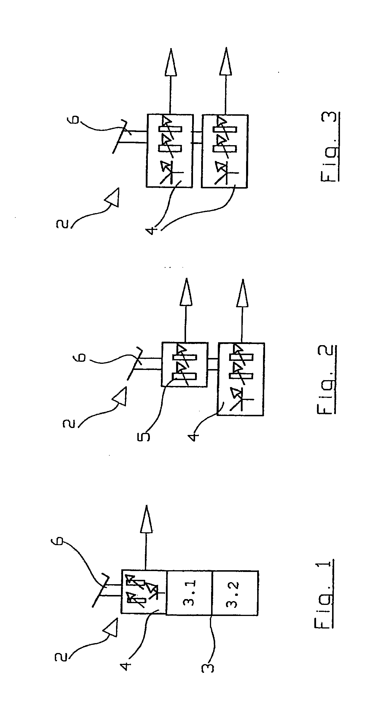
[0019]FIG. 1 shows a brake pedal unit 2, which has a pneumatic control valve 3 and a sensor 4, which is connected to a brake pedal 6 and which senses its position or movement. Sensor 4 is equipped with an intelligence of its own, i.e. it contains electronics that process the output signals of sensor elements, as will be explained further below. Electrical and pneumatic connectors of brake pedal unit 2 are left out for the purpose of clarity. Such a brake pedal unit is also suitable for example for a brake system according to the DE 103 57 373 84 document mentioned at the outset.

[0020]FIG. 2 shows a brake pedal unit 2 having two redundant sensors 4 and 5, of which sensor 4 in turn has an intelligence of its own in the form of an electronic circuit, while sensor 5 has no intelligence of its own. Such a brake pedal unit may be used for a “brake-by-wire” system.

[0021]Brake pedal unit 2 of FIG. 3 has two redundant sensors 4, which respectively have an intelligence of their own and are li...


PUM


Abstract

The brake system for motor vehicles has a brake pedal unit having a sensor, which has an intelligence of its own in the form of an electronic processing unit, which directly calculates actuating signals for brake actuators. Furthermore, the brake system has a central electronic control unit, which ascertains actuating signals for the actuators on the basis of an analog or digital signal of the mentioned sensor or of an additional sensor. The actuators have an intelligence of their own in the form of an electronic processing unit, which verifies whether the actuating signal coming from the central electronic control unit is valid. If this is the case, then the actuators are controlled by this signal, otherwise on the basis of the actuating signal calculated by the sensor.

Description

FIELD OF THE INVENTION[0001]The present invention relates to a brake system and to a method for controlling a vehicle brake.BACKGROUND INFORMATION[0002]German patent document DE 103 57 373 B4 discusses an electronic brake system for a vehicle having at least two brake circuits, which has a braking request recording device having two autonomous braking request recording means, one of which is connected to a central control unit while the other is connected to an autonomous brake circuit control system that is independent of the central electronic control unit. In the event of a failure of the central electronic control unit, the brake circuit control system in cooperation with the one braking request recording means assumes all activations of the vehicle brakes. The braking request recording means are sensors integrated into a brake pedal unit. This creates a certain redundancy.[0003]German patent document DE 19815440 A1 refers to providing for a braking value sensor and a part of a ...

Claims


Application Information

Patent Timeline
IPC IPC(8): B60T8/172
CPCB60T7/042B60T8/321B60T8/327B60T2270/82B60T2270/402B60T2270/404B60T2220/04
Inventor SZELL, PETERGIANONE, LASZLOSZABO, GERGELY
Owner KNORR-BREMSE SYST FUER NUTZFAHRZEUGE GMBH
Why Eureka
Try Eureka