Cleaning device for sunlight collecting devices in a solar thermal electric power generation system

Inactive Publication Date: 2011-06-02
KAWASAKI HEAVY IND LTD
View PDF9 Cites 41 Cited by
  • Summary
  • Abstract
  • Description
  • Claims
  • Application Information

AI Technical Summary

Benefits of technology

[0036]According to the present invention, the reflecting surfaces of the collectors can be cleaned by using air, which is inexhaustible in any region and, hence, a limitation by reason of cleaning equipment does not exist when selecting a place for installing a solar thermal electric power generation system. Further, there is no need t

Problems solved by technology

Deposition of dust and dirt forms a soiled portion on the reflecting surface, which reduces sunlight reflection efficiencies, thus resulting in a reduced collection of the solar thermal energy.
However, cleaning with water cannot be effected in a region where it is difficult to secure a water source having sufficient amount of water or in a place where it is difficult to get water from a water supply station.
Even when such a water source or the like is secured, in a place under a bad water supply condition, cleanin

Method used


Image

  • Cleaning device for sunlight collecting devices in a solar thermal electric power generation system
  • Cleaning device for sunlight collecting devices in a solar thermal electric power generation system
  • Cleaning device for sunlight collecting devices in a solar thermal electric power generation system

Examples


Example

[0059]Embodiments of a cleaning device for a solar thermal electric power generation system according to the present invention will be described with reference to the attached drawings.

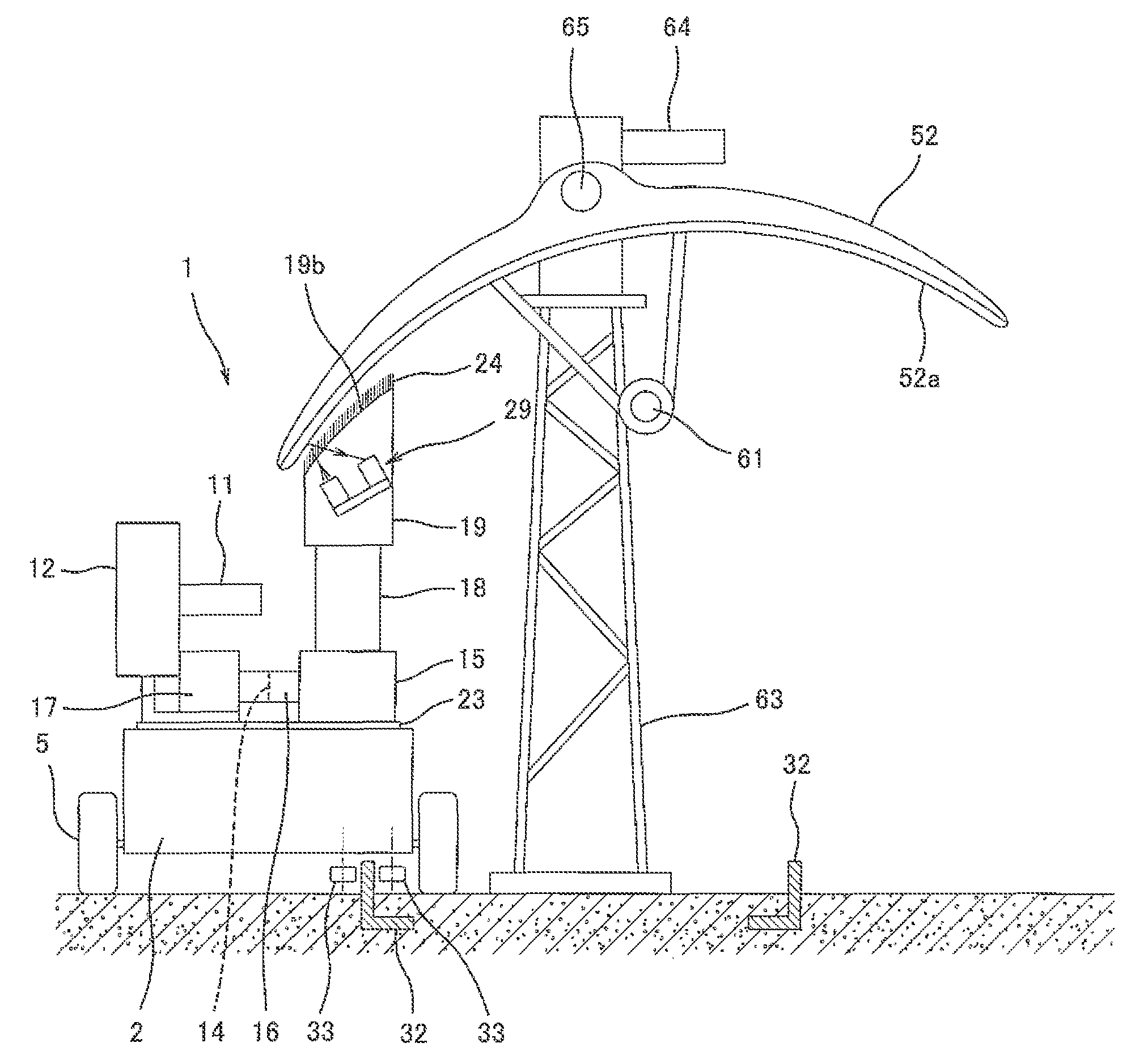
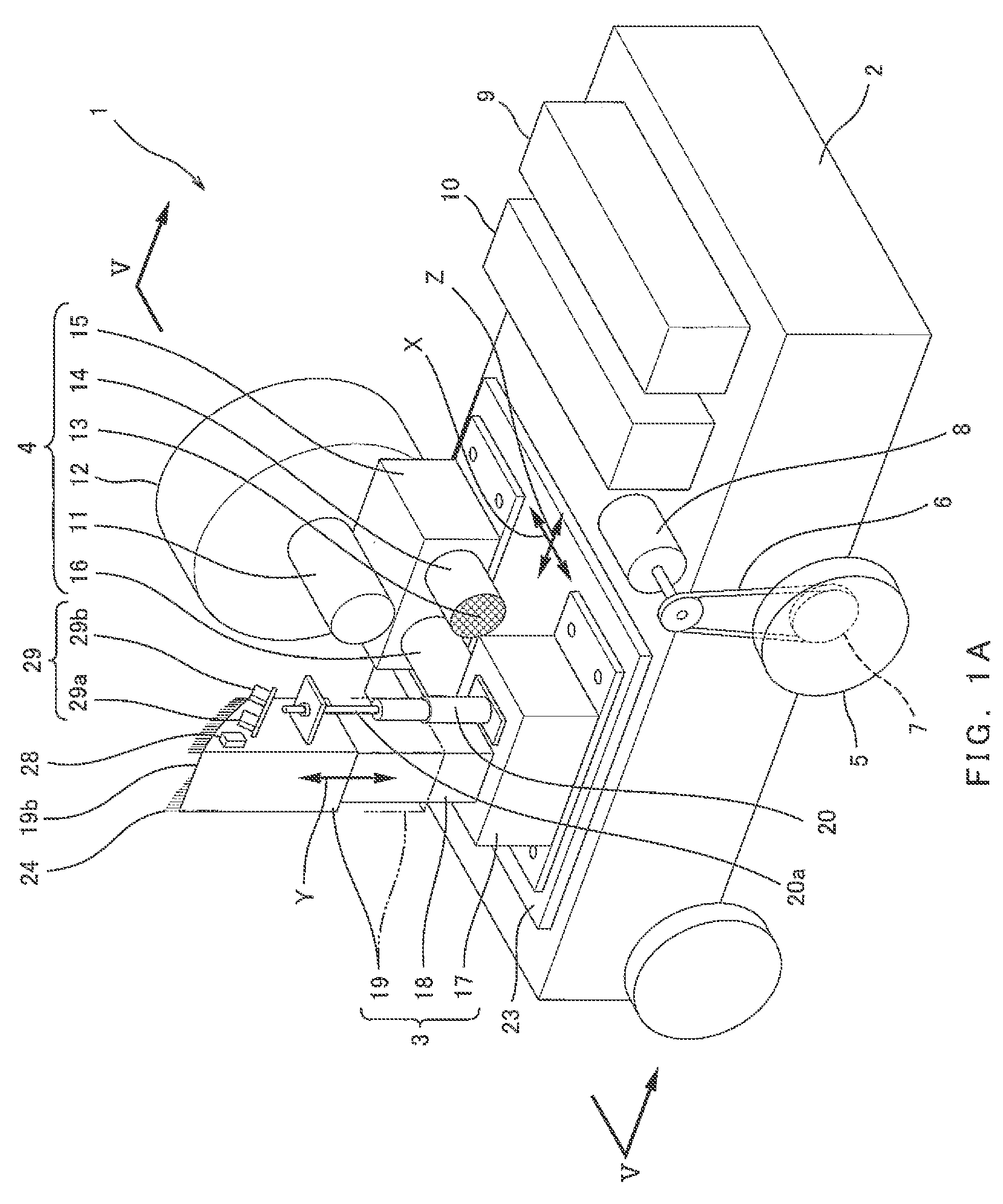
[0060]FIG. 11 shows a single parabolic trough type collector 52. The collector 52 shown in FIG. 11 has a reflecting surface 52a in a substantially horizontal orientation to the sun. The expression “orientation of the reflecting surface 52a”, as used herein, means an orientation of the normal to the reflecting surface 52a. The single collector (sunlight collecting device) 52 illustrated here is a unit having a total length of about 150 m which is assembled by joining twelve modules 62 each having an opening width of about 5.8 m and a length of about 12 m. Of course, these sizes are illustrative and are not limitative. The sizes are illustrated for understanding of a typical size of such a collector unit. FIGS. 5 to 8 are each a view showing a cleaning device 1 as viewed from a reverse side of the clean...


PUM


Abstract

A device for cleaning a collector of a solar thermal electric power generation system is provided which does not need to secure any water source or the like and which improves the flexibility of selection of a place for installing the solar thermal electric power generation system. The cleaning device includes an air supply device and an air nozzle configured to blow air supplied from the air supply device, which are mounted on a self-propelled truck. The cleaning device is capable of blowing air blown from the air nozzle against a sunlight reflecting surface of a collector to clean up the sunlight reflecting surface. The air nozzle is configured to be capable of moving up and down. The cleaning device further includes a soiling degree measuring device for measuring soiling degrees of the sunlight reflecting surface before and after air blowing by the air nozzle.

Description

TECHNICAL FIELD[0001]The present invention relates to a cleaning device for cleaning sunlight reflecting surfaces of sunlight collecting devices arranged in lines in a solar thermal electric power generation system. More specifically, the invention relates to a cleaning device for removing dust and dirt that are likely to deposit on the sunlight reflecting surfaces of such sunlight collecting devices.BACKGROUND ART[0002]Unlike electric power generation using fossil fuels, solar thermal electric power generation utilising solar thermal energy is a technique capable of satisfying energy demand without affecting the earth's environment. That is, solar energy is a stable zero-cost energy source taking the place of fossil fuels. Further, the adoption of solar thermal electric power generation system makes it possible to prevent a great deal of emissions of carbon dioxide, and hence can contribute to the prevention of global warming.[0003]FIG. 10 is a schematic view showing a solar therma...

Claims


Application Information

Patent Timeline
IPC IPC(8): B08B5/00F24S23/74
CPCB08B5/02F24J2/1047Y02E10/40F24J2/40F24J2/461F24S23/80F24S40/20F24S50/00
Inventor OTA, HIDEAKI
Owner KAWASAKI HEAVY IND LTD
Why Eureka
Try Eureka