Combustor panel arrangement

a technology of combustion panel and combustion chamber, which is applied in the direction of efficient propulsion technology, machines/engines, lighting and heating apparatus, etc., can solve the problems of high-temperature localized areas, near-stoichiometric combustion conditions, and inability to achieve high-temperature zones, etc., to achieve the effect of reducing the effects of maldistributed thermal loads

a technology of combustion panel and combustion chamber, which is applied in the direction of efficient propulsion technology, machines/engines, lighting and heating apparatus, etc., can solve the problems of high-temperature localized areas, near-stoichiometric combustion conditions, and inability to achieve high-temperature zones, etc., to achieve the effect of reducing the effects of maldistributed thermal loads

US20110126543A1Active Publication Date: 2011-06-02RTX CORP

Image

  • Combustor panel arrangement
  • Combustor panel arrangement
  • Combustor panel arrangement

Examples


Embodiment Construction

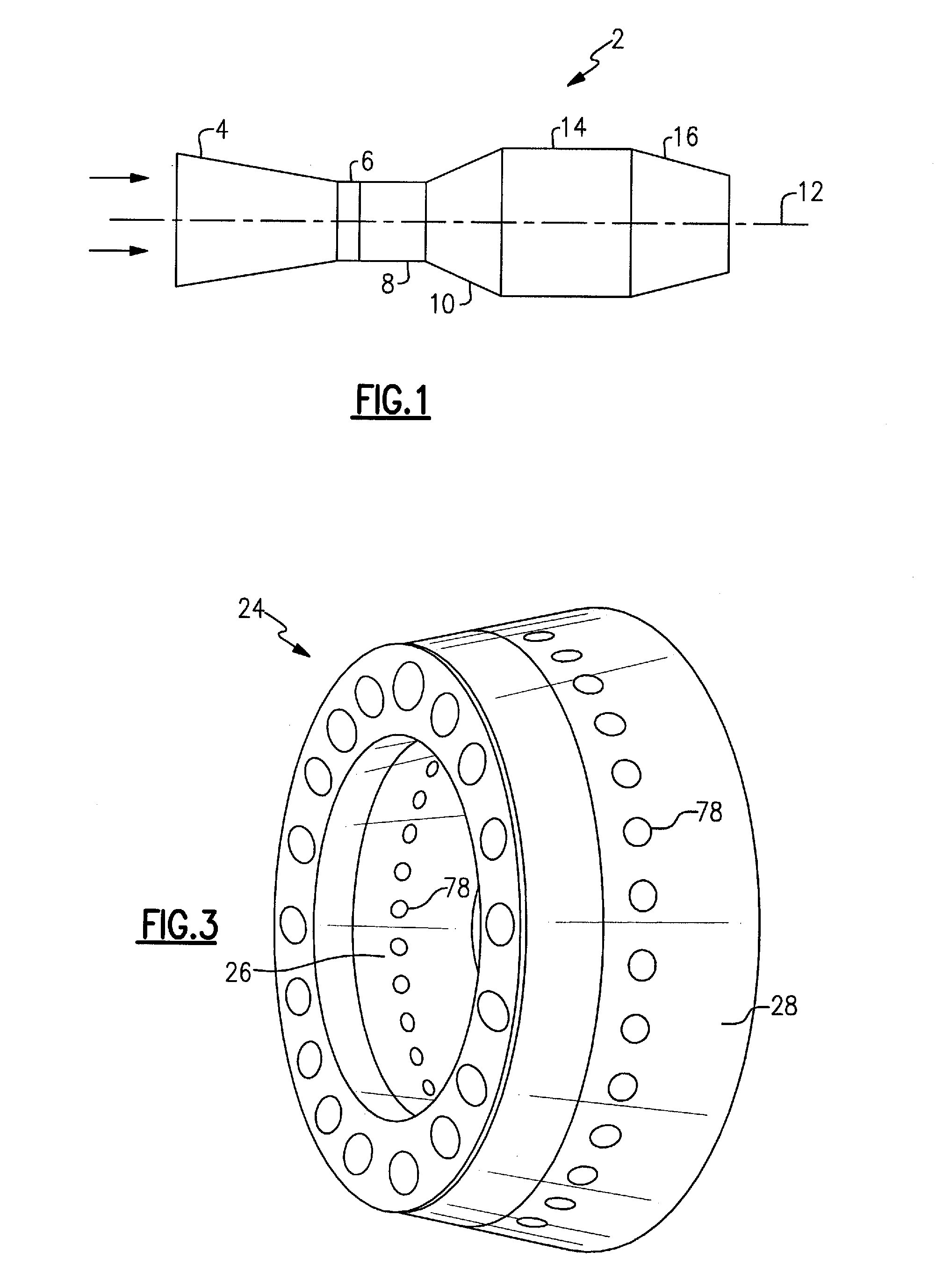
[0025]Referring to FIG. 1 of the drawings, a conventional gas turbine engine 2 generally includes a compressor module 4, a diffuser section 6, a combustor module 8, and a turbine module 10. The modules are disposed about a central longitudinal axis 12 which constitutes the centerline of the gas turbine engine. Gas flow through the gas turbine engine 2 is indicated by arrow F. Some gas turbine engines, such as those used in military applications, include an afterburner section 14 and a nozzle 16. On the other hand, some gas turbine engines such as those used large commercial jet liners of contemporary design include a high bypass ratio fan module (not shown) forward of the compressor module 4. It should be noted that small engines may have radial or centrifugal compressors, rather than axial compressors.

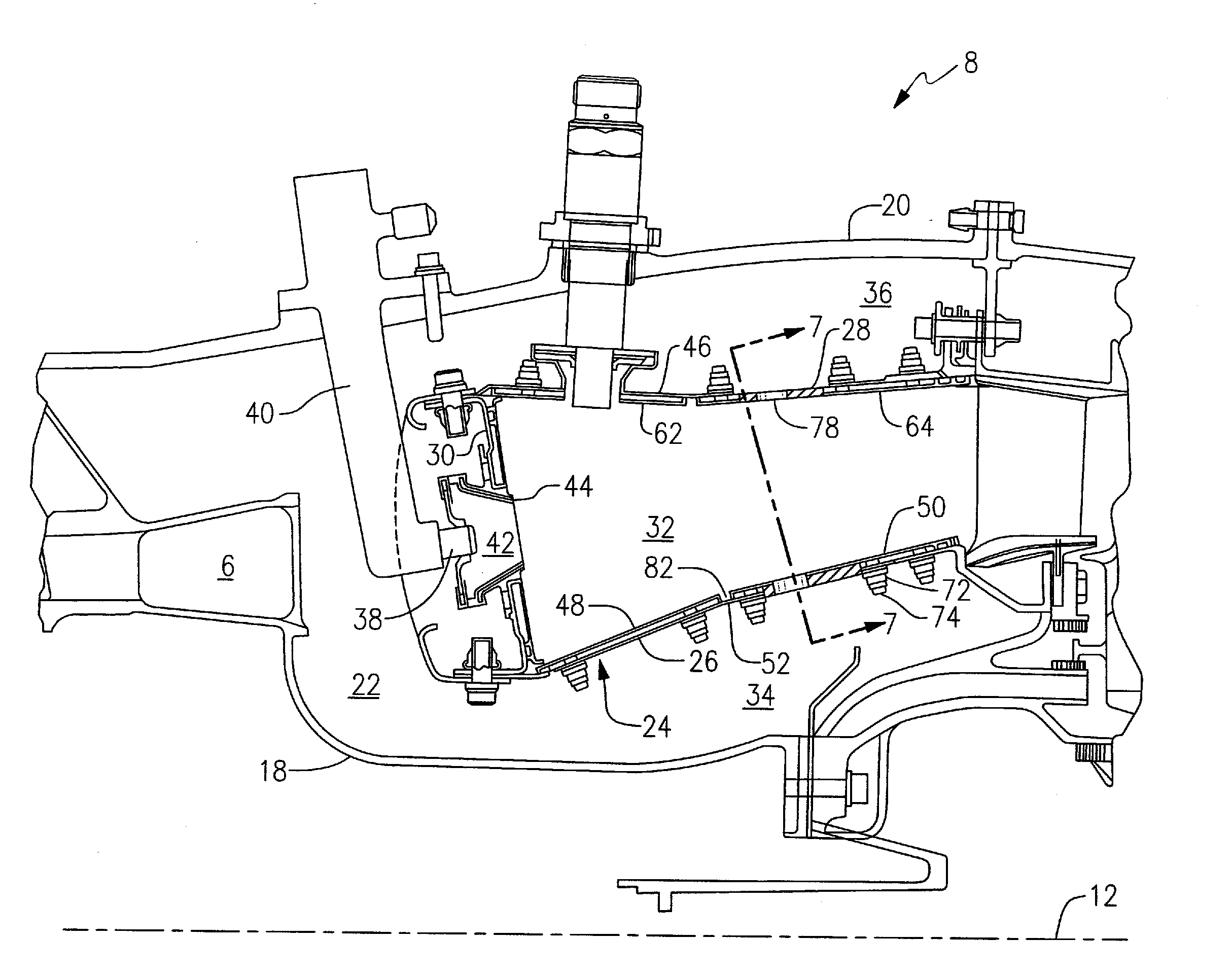
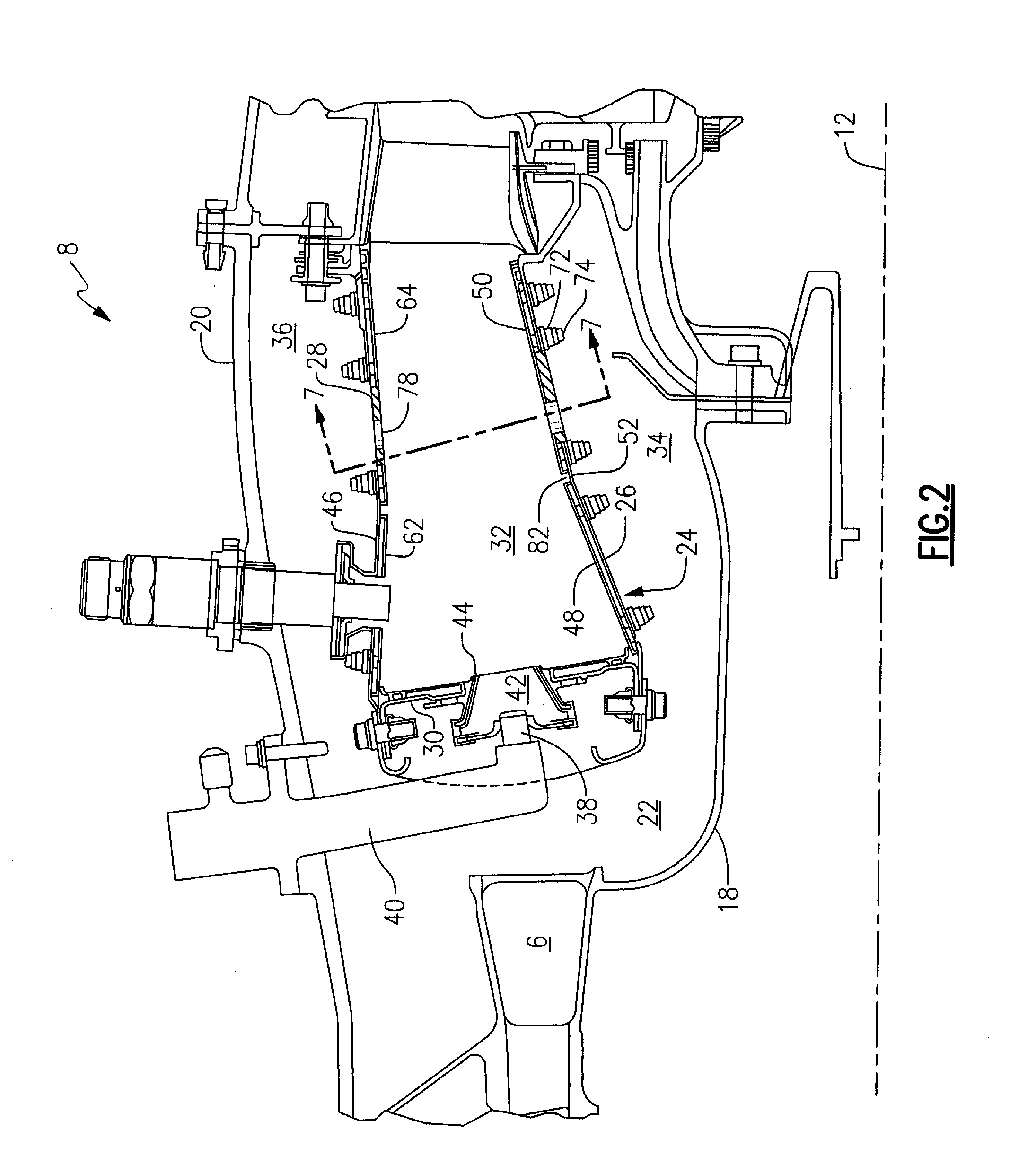
[0026]Referring now to FIGS. 2 and 3, the exemplary combustor module 8 includes a radially inner case 18 and a radially outer case 20 concentric with and circumscribing the inner case...


PUM


Abstract

A combustor module for a gas turbine engine is provided that includes a first annular liner assembly extending along a longitudinal axis of the engine. The first annular liner assembly includes a first annular support shell and a plurality of first heat shield panels coupled to the first annular support shell. The first heat shield panels form a segmented ring defining a plurality of first axial seams therebetween. The combustor module further includes a bulkhead coupled to the first annular liner assembly. The bulkhead provides a plurality of fuel nozzles for passing a first mass flow comprising fuel and air. The combustor module further includes a second annular liner assembly coupled to the bulkhead. The second annular liner assembly is in spaced-apart generally coaxial relationship from the first annular liner assembly by a channel height H. The second annular liner assembly includes an air admittance hole having a mean diameter D extending along a hole axis. The hole axis is offset from the first axial seam defined by the first heat shield panels.

Description

STATEMENT OF GOVERNMENT INTEREST[0001]The United States Government has certain rights in this disclosure pursuant to contract number N00019-02-C-3003 between the United States Navy and United Technologies Corporation.FIELD OF THE DISCLOSURE[0002]This disclosure relates generally to combustors for gas turbine engines and, more particularly, to a heat shield panel arrangement for use in double wall gas turbine combustors.BACKGROUND OF THE DISCLOSURE[0003]Gas turbine engines, such as those used to power modem commercial aircraft, include a compressor for pressurizing a supply of air, a combustor for burning a hydrocarbon fuel in the presence of the pressurized air, and a turbine for extracting energy from the resultant combustion gases. In aircraft engine applications, the compressor, combustor and turbine are disposed about a central engine axis with the compressor disposed axially upstream of the combustor and the turbine disposed axially downstream of the combustor.[0004]An exemplar...

Claims


Application Information

Patent Timeline
02 Jun 2011
Publication
US20110126543A1
IPC
F02C7/22; F02C3/14
CPC
F23R3/002; Y02T50/675; F23R2900/03041; Y02T50/60
Inventors
KIRSOPP, PHILIP J.; DORNBACK, AARON J.