Auto Bending Structure of Sunshade

a technology of sunshade and bending structure, which is applied in the direction of umbrellas, traveling accessories, apparel, etc., can solve the problems of high production cost, inflexible rotation, and difficult scarf joint, etc., and achieves more balanced bending, lower cost, and simple structure

Active Publication Date: 2011-06-02
PHAETON MFG LLC
View PDF9 Cites 10 Cited by
  • Summary
  • Abstract
  • Description
  • Claims
  • Application Information

AI Technical Summary

Benefits of technology

[0005]The present invention is firstly intended to provide an auto bending structure of sunshade with simpler structure and lower cost according to the current arts.
[0014]As a further improvement, the bottom of said sliding rod is pivotally connected with the top of said first connecting rod, while the bottom of said first connecting rod is pivotally connected with the top of the second connecting rod in the lower section of the umbrella stem, the bottom of said second connecting rod is pivotally connected with the lower sliding plug in the lower section of the umbrella stem, the lower return spring is supported between the lower section of bending and the lower sliding plug. Thus, the return spring force is increased with the connecting rod and the lower return spring so that the direction adjustment between the upper section of bending and the lower section of bending is easier.
[0019]Compared with existing technologies, the present invention is advantageous in that: in the steering mechanism, not so many pulleys, torsion springs and other elastic parts are required, and thus fewer parts, simpler structure and lower cost are achieved; in particular, it is provided with the pulley-type labor saving mechanism and integrates the upper and lower return springs as well as the upper and lower sliding plug, therefore, the whole structure can allow smooth and labor-saving operation of the umbrella, besides, since the umbrella string is wound for multiple times, the sliding rod will move a unit distance after the umbrella string moving multiple units of distance, thus ensuring more balanced bending and make the whole mechanism more practical.

Problems solved by technology

The biggest disadvantage of the traditional bending device is that the bending angle of the upper protruding connector cannot reach the proper angle for scarf joint due to the load of the sunshade supported by the upper umbrella stem, in particular, due to the load of the sunshade, excessive bending will be caused once the scarf rod is detached from the scarf slot, which will cause difficulty in scarf joint.
It is advantageous in graceful appearance, simple operation, durability and the ability of free positioning within the range of 0˜28°, however, it is disadvantageous in complicated structure, high production cost, lack of a labor-saving mechanism, inflexible rotation etc. and needs to be improved.

Method used


Image

  • Auto Bending Structure of Sunshade
  • Auto Bending Structure of Sunshade
  • Auto Bending Structure of Sunshade

Examples


embodiment 1

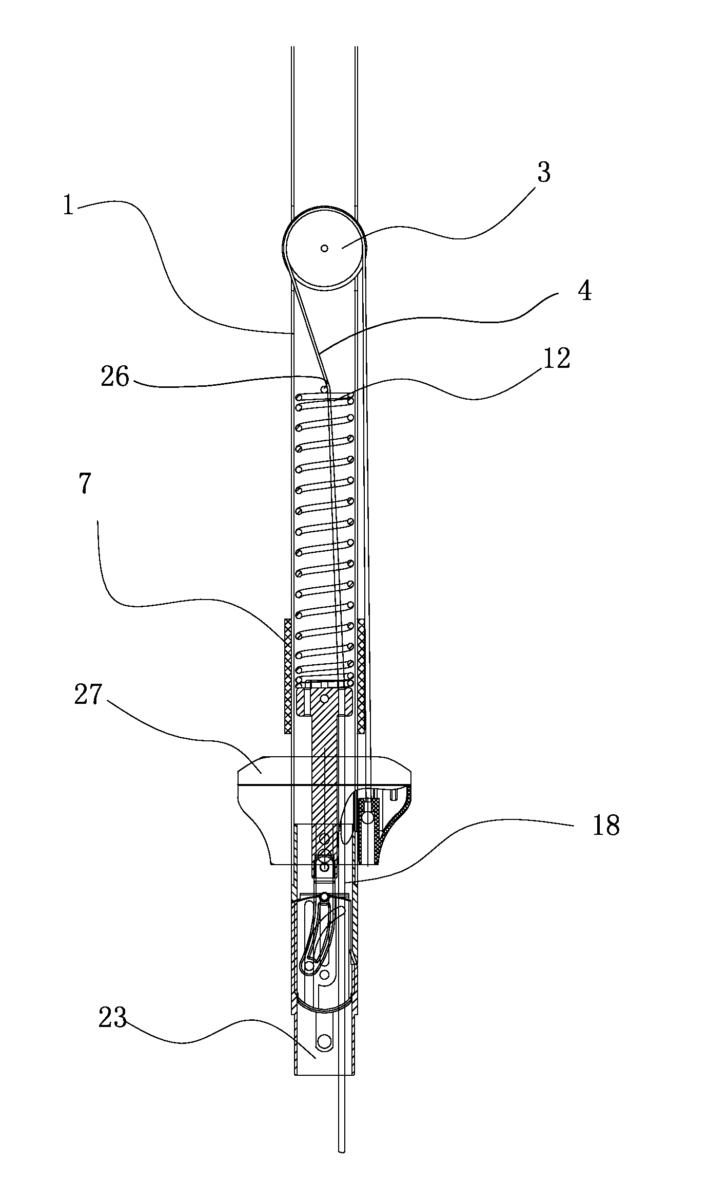
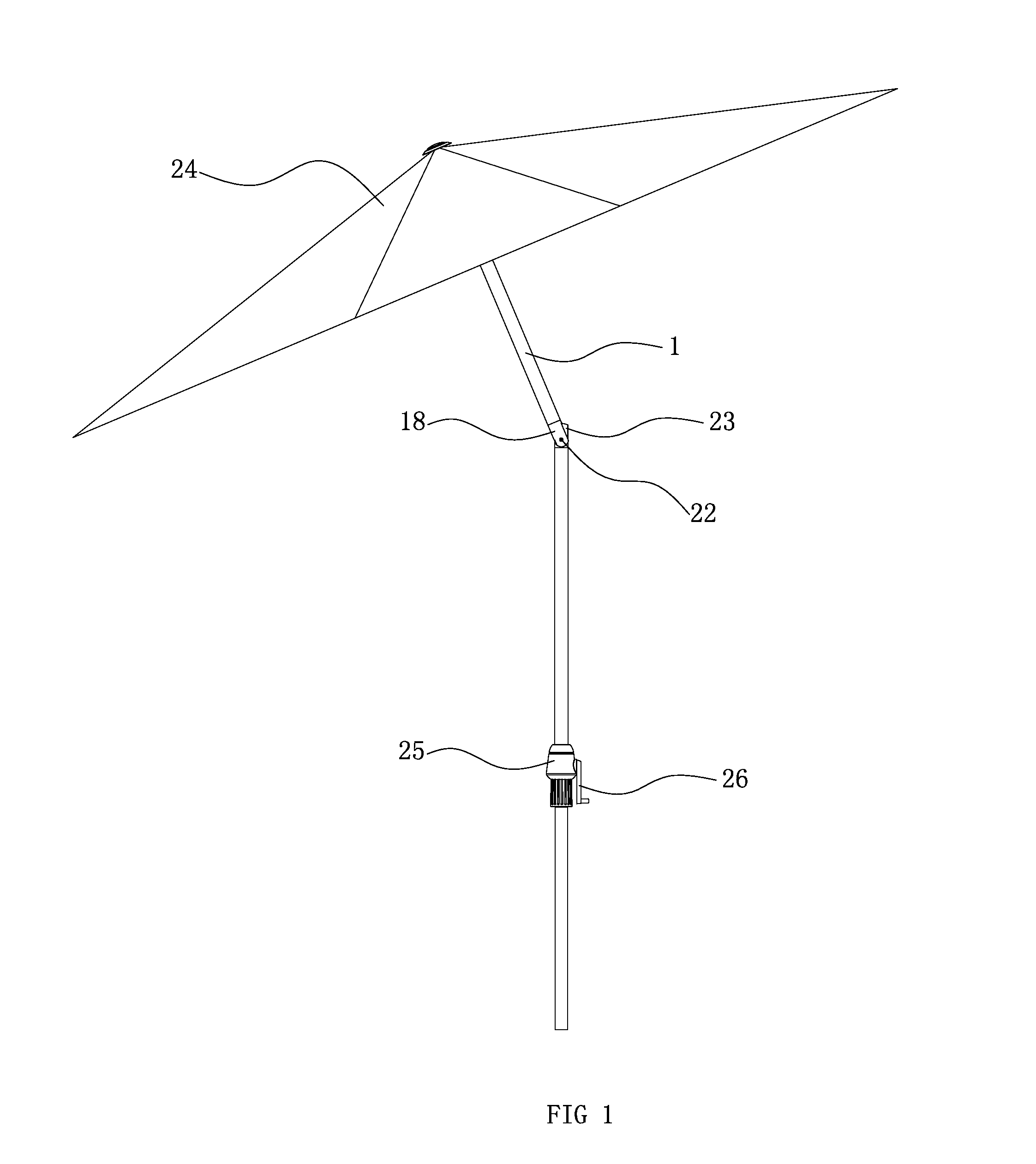
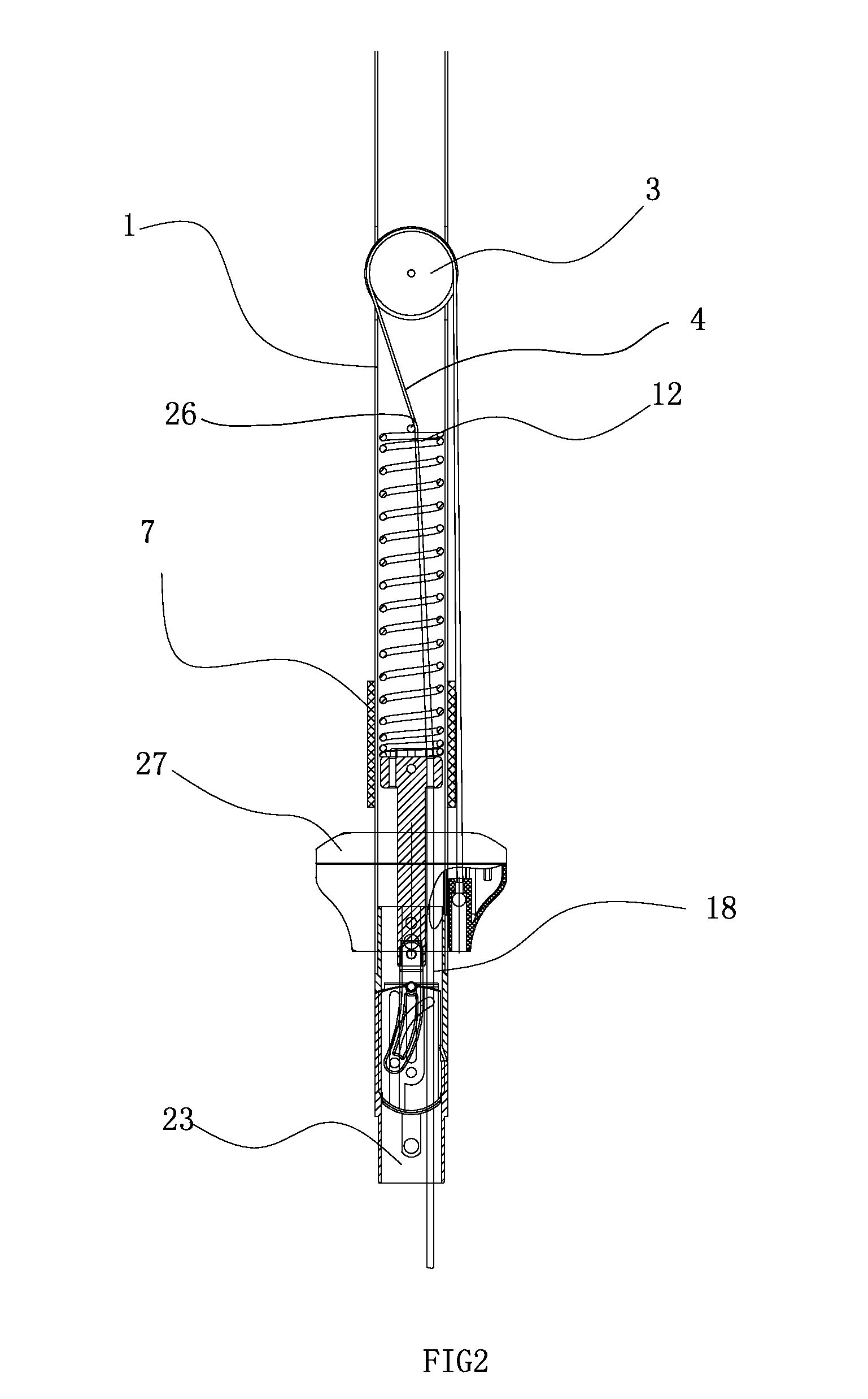
[0034]As shown in FIGS. 1-5, an auto bending structure of sunshade comprises the upper section of bending 18, lower section of bending 23, upper section of umbrella stem 1 and umbrella string 4, etc, both sides of one end of lower section of bending 18 are cut even into a flat scarf joint part 23.1, which is provided with a through hole 23.2 in the middle, 2 arc groove 23.3 are provided on both sides of the scarf joint part 23.1 of said lower section of bending 23, a slot 18.1 is provided on the top of said upper section of bending 18, said slot 18.1 corresponds to the scarf joint part 23.1 of said lower section of bending 23, through holes 18.2 are provided on both sides of slot 18, scarf joint part 23.1 of said lower section of bending 23 is embedded in slot 18.1, pivotally connected the lower section of bending 23 and upper section of bending 18 with the rivet 22 so allow rotation between said lower section of bending 23 and upper section of bending 18, slot 18.1 of the upper sec...

embodiment 2

[0035]As shown in FIGS. 6-9, said auto bending structure of sunshade comprises the upper section of bending 18, lower section of bending 23, upper section of umbrella stem 1, fixed plug 5, upper sliding plug 17, the umbrella string 4, the umbrella fabric 24 and the umbrella frame, etc.

[0036]Both sides of one end of the lower section of bending 23 are cut even into a flat scarf joint part 23.1, which is provided with a through hole 23.2 in the middle, 2 arc groove 23.3 are provided on both sides of the scarf joint part 23.1 of said lower section of bending 23, a slot 18.1 is provided on the top of said upper section of bending 18, said slot 18.1 and scarf joint part 23.1 of said lower section of bending 23 are corresponding, through holes 18.2 are provided on both sides of slot 18, s scarf joint part 23.1 of said lower section of bending 23 is embedded in slot 18.1, through hole 23.2 passing through the lower section of bending 23 via rivet 22 and the through hole 18.2 of the upper s...

embodiment 3

[0042]As shown in FIGS. 10-13, said auto bending structure of sunshade comprises the upper section of bending 18, lower section of bending 23, upper section of umbrella stem 1, fixed plug 5, upper sliding plug 17, lower sliding plug 32, first connecting rod 27, second connecting rod 29 as well as the umbrella string 4, the umbrella fabric 24 and the umbrella frame, etc.

[0043]Both sides of one end of the lower section of bending 23 are cut even into a flat scarf joint part 23.1, which is provided with a through hole 23.2 in the middle, 2 arc groove 23.3 are provided on both sides of the scarf joint part 23.1 of said lower section of bending 23, a slot 18.1 is provided on the top of said upper section of bending 18, said slot 18.1 and scarf joint part 23.1 of said lower section of bending 23 are corresponding, through holes 18.2 are provided on both sides of slot 18, s scarf joint part 23.1 of said lower section of bending 23 is embedded in slot 18.1, through hole 23.2 passing through...


PUM


Abstract

An auto bending structure of sunshade comprising an upper section of bending and a lower section of bending movably riveted featuring that: a sliding rod is provided in the pivotally connected upper section of bending and lower section of bending, through holes are provided on the top and bottom of said sliding rod, the through hole on the bottom of said sliding rod is provided with a guide pin, an arc groove for said guide pin to slide on is provided on the scarf joint part of the lower section of bending, linear groves corresponding to said arc groove for said guide pin to slide on are provided on both sides of said groove of the upper section of bending, a sliding sleeve with a through hole on the bottom is provided on the top of said sliding rod, said through hole on the bottom of said sliding sleeve corresponds to the through hole on the top of said sliding rod, correspondingly, the upper section of umbrella stem is provided with a linear groove on the outer wall and is surrounded by a ring, which is connected with the sliding rod and the sliding sleeve with the connecting pin, which slides in the linear groove to make the ring cooperate with the lower nest moving up and down and pulled by the umbrella string; the present invention is advantageous in simpler structure and lower production cost.

Description

CROSS REFERENCE TO RELATED PATENT APPLICATION[0001]The present invention claims the priority of Chinese Patent No. 201020556192.1 filed on Oct. 8, 2010, which application is incorporated herein by reference.FIELD OF THE INVENTION[0002]The present invention relates to an automatic bending structure of an auto bending structure of sunshade.BACKGROUND OF THE INVENTION[0003]A traditional sunshade bending positioning device consists of the upper protruding connector, lower concave connector, the positioning rod, the spring pin and the spring, etc. The biggest disadvantage of the traditional bending device is that the bending angle of the upper protruding connector cannot reach the proper angle for scarf joint due to the load of the sunshade supported by the upper umbrella stem, in particular, due to the load of the sunshade, excessive bending will be caused once the scarf rod is detached from the scarf slot, which will cause difficulty in scarf joint.[0004]The auto bending mechanism for ...

Claims


Application Information

Patent Timeline
Patent Type & Authority Applications(United States)
IPC IPC(8): A45B17/00
CPCA45B17/00A45B2025/146A45B2023/0012A45B25/06
Inventor LUO, XIONG
Owner PHAETON MFG LLC
Why Eureka
Try Eureka