
Pneumatic tire

a technology of pneumatic tires and tires, applied in the field of pneumatic tires, can solve the problems of tire having a high rolling resistance and a great weight, tire hindering the vehicle from taking a low fuel consumption, and damage to the handling stability, and achieves excellent performan

Inactive Publication Date: 2011-06-02
SUMITOMO RUBBER IND LTD
View PDF1 Cites 0 Cited by
  • Summary
  • Abstract
  • Description
  • Claims
  • Application Information

AI Technical Summary

Benefits of technology

[0011]It is an object of the present invention to provide a pneumatic tire which is excellent in various performances.
[0013]The cord of the reinforcing layer suppresses a deformation of the tread in the vicinity of the main groove. The reinforcing layer contributes to a handling stability.

Problems solved by technology

By the deformation, a handling stability is damaged.
However, the tire has a high rolling resistance and a great weight.
The tire hinders a vehicle from taking a low fuel consumption.
A tire having a high vertical stiffness takes a poor ride comfort.

Method used


Image

  • Pneumatic tire
  • Pneumatic tire
  • Pneumatic tire

Examples


example 1

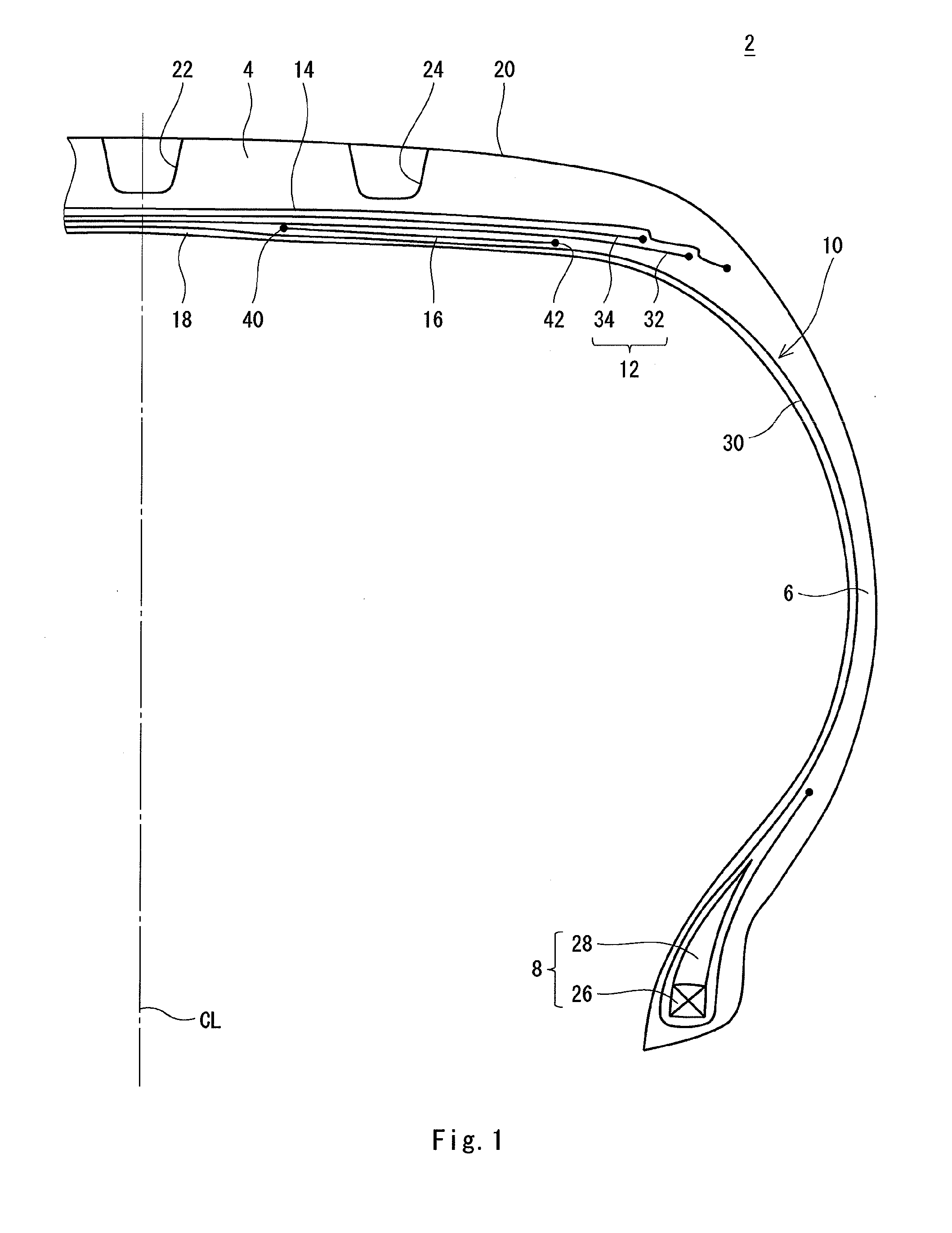
[0062]There was manufactured a tire for a passenger car which has the structure shown in FIGS. 1 to 4. The tire has a size of “195 / 65R15”. A specification of the tire is as follows.

[0063]Tread[0064]Width Wg of main groove: 8 mm

[0065]Carcass[0066]Material of cord: nylon[0067]Fineness of cord: 1670 dtex / 2[0068]Angle of cord with respect to circumferential direction: 90°

[0069]Belt[0070]Material of cord: steel[0071]Structure of cord: 2+2[0072]Filament diameter of cord: 0.23 mm[0073]Angle of cord with respect to circumferential direction: 26°

[0074]Band[0075]Material of cord: nylon[0076]Fineness of cord: 1400 dtex / 2[0077]Angle of cord with respect to circumferential direction: approximately 0°

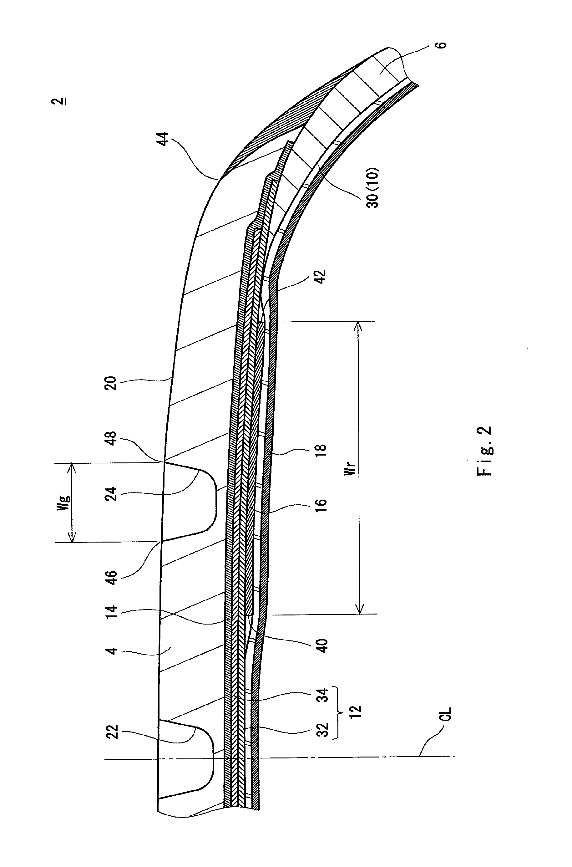
[0078]Reinforcing layer[0079]Material of cord: steel[0080]Structure of cord: 2+2[0081]Filament diameter of cord: 0.23 mm[0082]Angle of cord with respect to circumferential direction: 90°[0083]Width Wr: 25 mm

examples 2 to 8

[0084]A tire according to each of examples 2 to 8 was obtained in the same manner as in the example 1 except that a width Wr was set as shown in the following Table 1.

examples 9 to 14

[0087]A tire according to each of examples 9 to 14 was obtained in the same manner as in the example 1 except that a position of a reinforcing layer was set as shown in the following Table 2. Symbols (A) to (E) in the Table 2 have the following meaning:

[0088](A) Between the carcass 10 and the belt 12;

[0089](B) Between the inner liner 18 and the carcass 10;

[0090](C) Between the inner layer 32 of the belt 12 and the outer layer 34 of the belt 12;

[0091](D) Between the belt 12 and the band 14; and

[0092](E) Between the band 14 and the tread 4.


PUM


Abstract

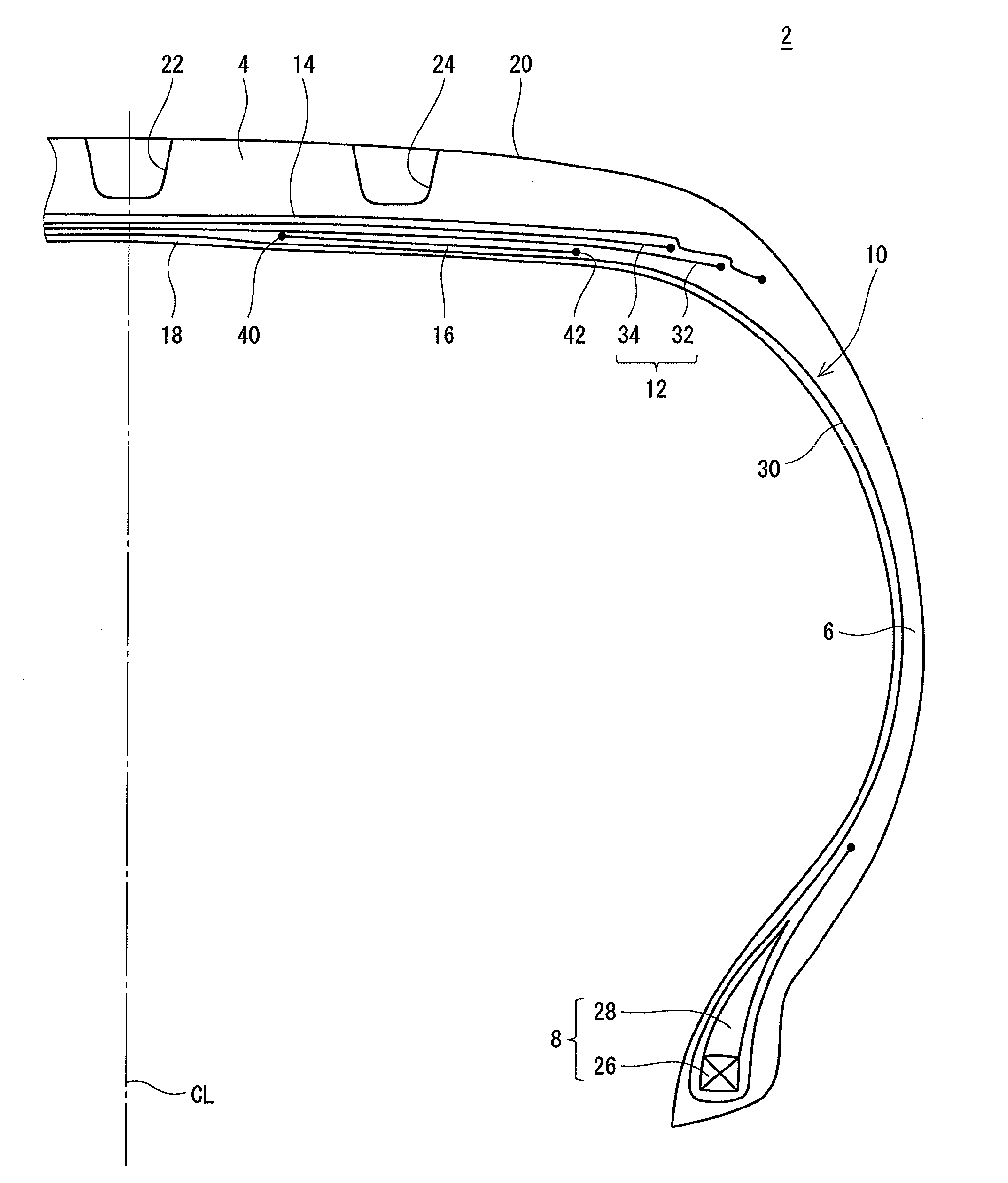
A pneumatic tire (2) includes a tread (4), a sidewall (6), a bead (8), a carcass (10), a belt (12), a band (14), a reinforcing layer (16), and an inner liner (18). The tread (4) has a shoulder main groove (24). The reinforcing layer (16) is present locally in an axial direction. The reinforcing layer (16) is positioned between the carcass (10) and the belt (12) in a radial direction. The reinforcing layer (16) is positioned on an inside in the radial direction with respect to the shoulder main groove (24). The reinforcing layer (16) is formed by a large number of cords provided in parallel and a topping rubber. The respective cords are extended substantially in the axial direction. A width (Wr) of the reinforcing layer (16) is equal to or higher than 200% of a width (Wg) of the shoulder main groove (24) and is equal to or lower than 500% of the width (Wg) of the shoulder main groove (24).

Description

[0001]This application claims priority on Patent Application No. 2009-270934 filed in JAPAN on Nov. 30, 2009, the entire contents of which are hereby incorporated by reference.BACKGROUND OF THE INVENTION[0002]1. Field of the Invention[0003]The present invention relates to a pneumatic tire to be attached to a passenger car or the like.[0004]2. Description of the Related Art[0005]A tire includes a tread, a sidewall, a bead, a carcass, a belt and the like. The belt is formed by an inner layer and an outer layer. Each of the inner and outer layers is constituted by a large number of cords provided in parallel and a topping rubber. Each of the cords is tilted with respect to an equator plane. The belt contributes to a stiffness of the tire.[0006]The tread has a plurality of main grooves. Each of the main grooves is extended in a circumferential direction. The main groove contributes to a drainage. By the main grooves, a surface of the tread is separated.[0007]In cornering of a vehicle, a...

Claims


Application Information

Patent Timeline
Patent Type & Authority Applications(United States)
IPC IPC(8): B60C9/18
CPCB60C9/2009Y10T152/10765B60C2009/2041
Inventor MATSUI, HIROSHIHE, CHUNLIANG
Owner SUMITOMO RUBBER IND LTD
Learn More