Coulomb Friction Damped Disc Brake Caliper Bracket

a friction damped disc and brake caliper technology, applied in the direction of noise/vibration control, slack adjusters, braking elements, etc., can solve the problems of corrosion at the interface of the two surfaces, the need to overcome the corrosion of the brake squeal countermeasures, and the inability to generate brake squeal undetectedly, so as to reduce the noise of the brake squeal and other problems

Inactive Publication Date: 2011-06-02
GM GLOBAL TECH OPERATIONS LLC
View PDF18 Cites 8 Cited by
  • Summary
  • Abstract
  • Description
  • Claims
  • Application Information

AI Technical Summary

Benefits of technology

[0014]The Coulomb friction damped disc brake caliper bracket according to the present invention has at least one Coulomb friction bar welded to the external surface of the disc brake caliper bracket, preferably disposed at one or both of the inboard and outboard tie-bars, and most preferably disposed at the outboard tie-bar. The Coulomb friction bar has an inner surface in abutting contact with the external surface of the tie-bar, whereby because of peripheral welding in the form of continuous welding along the peripheral edge of the Coulomb friction bar, corrosion cannot find entry into the interfacial boundary between the two surfaces, yet the two surfaces are free to vibrate one as to the other in Coulomb friction fashion to thereby provide damping and reduction of brake squeal and other noise.
[0015]The Coulomb friction damped disc brake caliper bracket according to the present invention provides an interfacial boundary between the Coulomb friction bar inner surface and the tie-bar external surface, wherein by “interfacial boundary” is meant a mechanically distinguishable surface boundary between two surfaces which are in mutual contact such that a state of Coulomb friction exists therebetween. In this regard, it is further believed that the interfacial boundary has the following attributes: 1) the greater the surface area of the interfacial boundary, the greater will be the damping; 2) the greater the number of interfacial boundaries, the greater will be the damping; 3) pre-tensioning and / or pre-loading is not required so long as the interfacial boundary provides Coulomb friction damping; and 4) the peripheral welding will not impair the Coulomb friction process at the interfacial boundary.

Problems solved by technology

Brake squeal can be undesirably generated at the brake corner when braking occurs, particularly in the frequency range from 2 kHz to 6 kHz.
And unfortunately, brake corners for performance motor vehicles, or those motor vehicles with high friction lining materials, are resistant to the prior art brake squeal countermeasures, due to the high amount of modal excitation from the friction material of the brake pads.
While the aforementioned U.S. Patent Application Publication US2007 / 0023240A1 solves the problem of brake squeal by use of Coulomb friction, a problem that needs to be overcome is that of corrosion at the interface of the two surfaces.

Method used


Image

  • Coulomb Friction Damped Disc Brake Caliper Bracket
  • Coulomb Friction Damped Disc Brake Caliper Bracket
  • Coulomb Friction Damped Disc Brake Caliper Bracket

Examples


example i

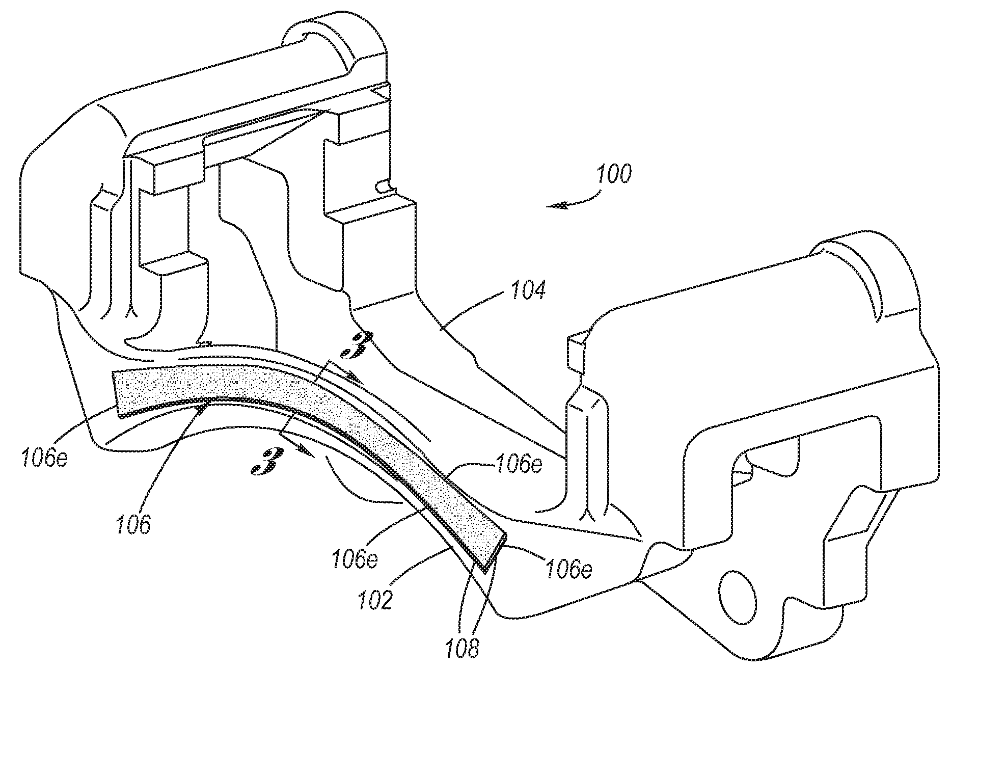
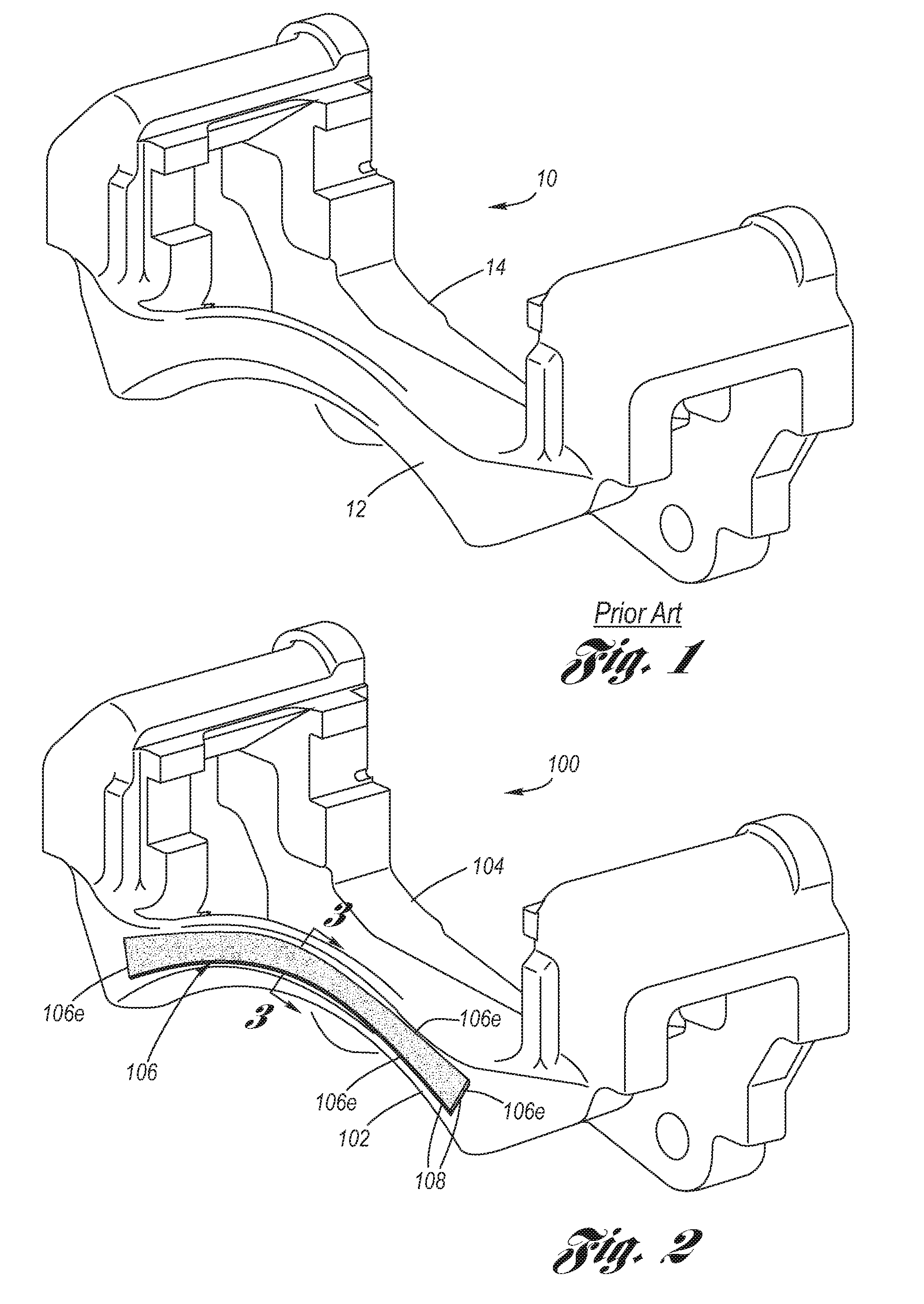
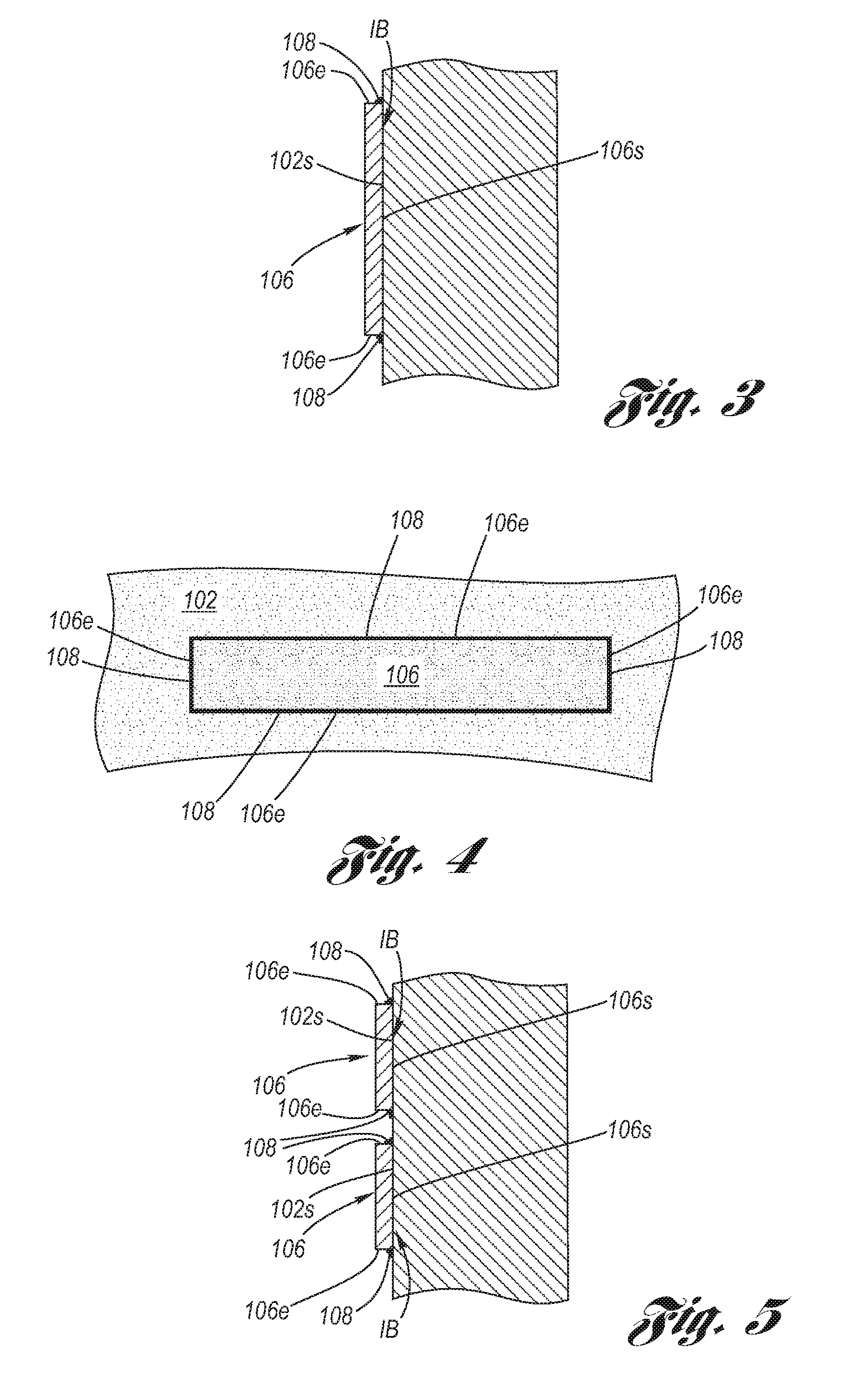
[0029]A pair of production disc brake rear wheel corner caliper brackets were used, one of them being modified into a prototype disc brake rear wheel corner caliper bracket having a Coulomb friction bar peripherally welded to the outboard tie-bar. Damping measurements were taken on the remaining production disc brake caliper bracket and the prototype disc brake caliper bracket, and the following damping levels were measured:

Caliper Bracket1st Tie-Bar Mode2nd Tie-Bar ModeProduction0.200.09Prototype0.350.12

[0030]It is seen that for the first tie-bar modal excitations, a 75% increase was shown for the prototype disc brake caliper bracket as compared to the production disc brake caliper bracket; and that for the second tie-bar modal excitations, a 33% increase was shown for the prototype disc brake caliper bracket as compared to the production disc brake caliper bracket. These increases reflect the Coulomb friction damping provided by the presence of the peripherally welded Coulomb fric...


PUM


Abstract

A Coulomb friction damped disc brake caliper bracket, wherein damping is provided by Coulomb friction, most preferably at the outboard tie-bar thereof, by a Coulomb bar peripherally welded thereto. An inner surface of the Coulomb friction bar is in abutting contact with the external surface of the tie-bar, whereby because of the continuous peripheral edge welding, corrosion cannot find entry into the interface of the two surfaces, yet the two surfaces form are free to vibrate one as to the other in Coulomb friction fashion to thereby provide damping and reduction of brake squeal and other noise.

Description

TECHNICAL FIELD[0001]The present invention relates to disc brake caliper brackets used in automotive applications, and more particularly to Coulomb friction damped disc brake caliper brackets.BACKGROUND OF THE INVENTION[0002]Motor vehicle disc brake systems utilize a disc brake unit, composed of a disc brake rotor and a disc brake caliper, at each respective wheel.[0003]The disc brake rotor typically includes a rotor hat for connecting to an axle hub of a rotatable axle of the motor vehicle, and at least one annular rotor cheek connected to the rotor hat, wherein the at least one rotor cheek has a pair of mutually opposed braking surfaces onto which brake pads are selectively applied when braking is desired. Typically, the rotor cheek configuration may be solid, in which case a single rotor cheek has opposing braking surfaces thereon, or may be vented, in which case a pair of rotor cheeks are mutually separated by a web of ventilation vanes and each rotor cheek provides a respective...

Claims


Application Information

Patent Timeline
Patent Type & Authority Applications(United States)
IPC IPC(8): F16D65/14
CPCF16D2055/0008F16D65/0006
Inventor LOWE, BRENT D.RIEFE, MARK T.DESSOUKI, OMAR S.SUNDAR, MOHANYANG, CHIA N.
Owner GM GLOBAL TECH OPERATIONS LLC
Why Eureka
Try Eureka