
Stiffener for Vehicle

a technology for vehicles and fenders, applied in the direction of roofs, bumpers, pedestrian/occupant safety arrangements, etc., can solve the problems of increasing and achieve the effect of reducing the injury of pedestrians

Active Publication Date: 2011-06-02
HYUNDAI MOTOR CO LTD +1
View PDF9 Cites 8 Cited by
  • Summary
  • Abstract
  • Description
  • Claims
  • Application Information

AI Technical Summary

Benefits of technology

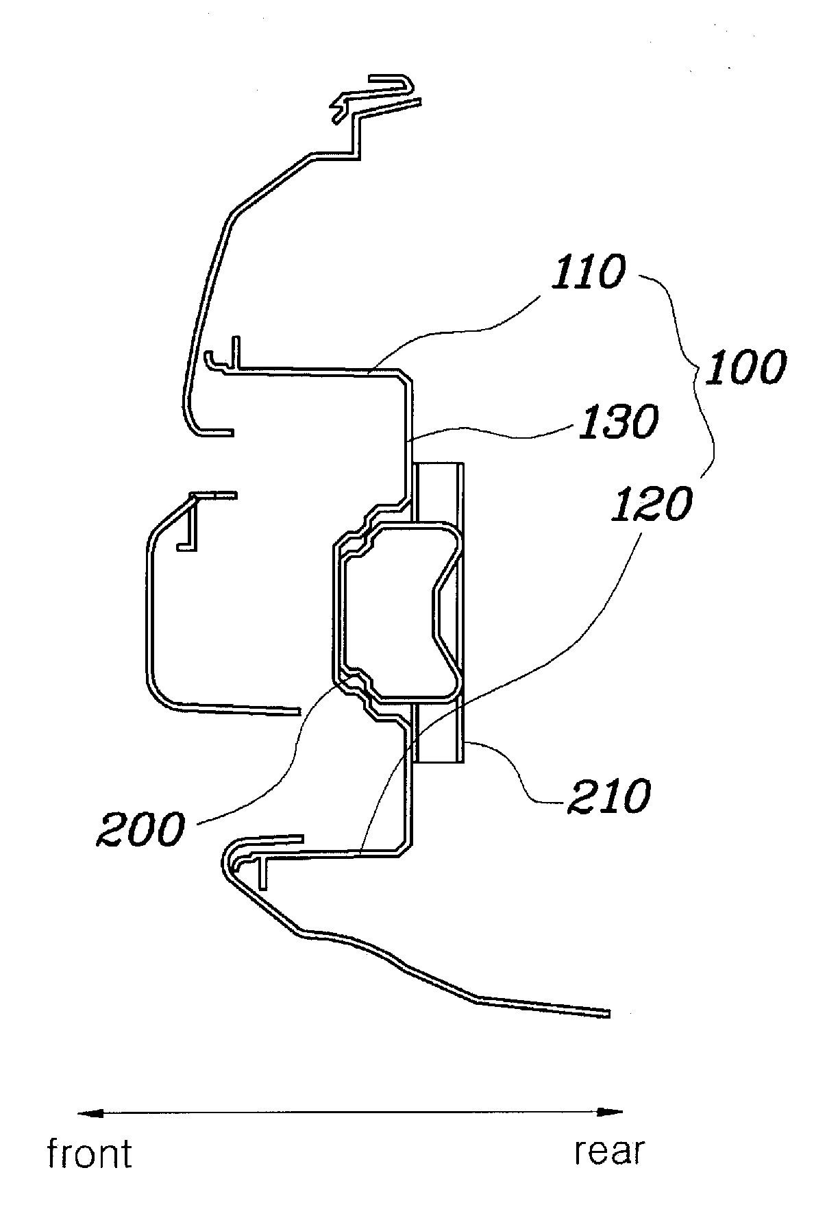
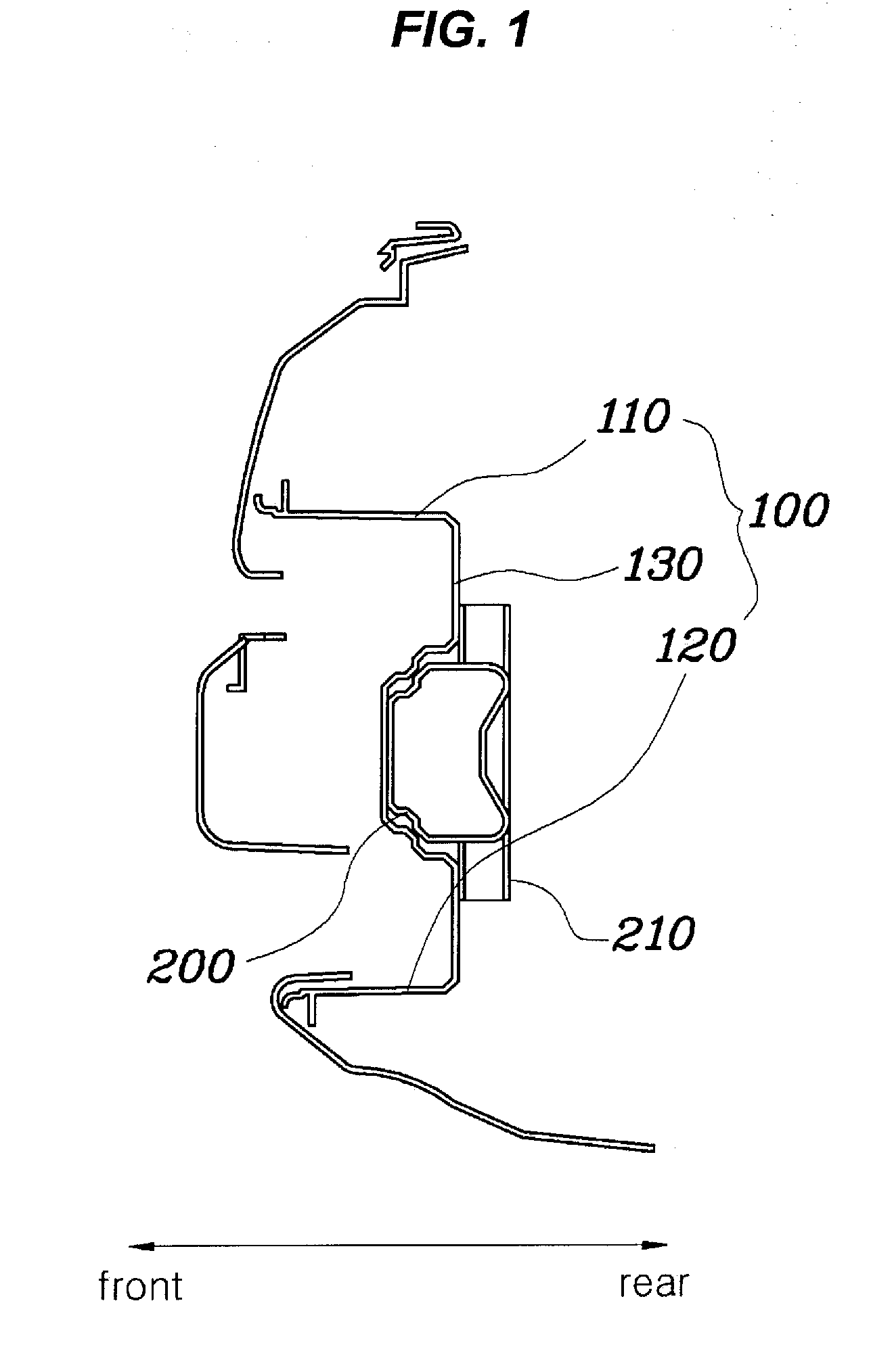
Various aspects of the present invention are directed to provide a stiffener for a vehicle, which absorbs shocks acting on the upper and lower portions of a pedestrian's leg in the event of a collision between the vehicle and the pedestrian, thus reducing the extent of injury to the pedestrian when he or she collides with the vehicle.
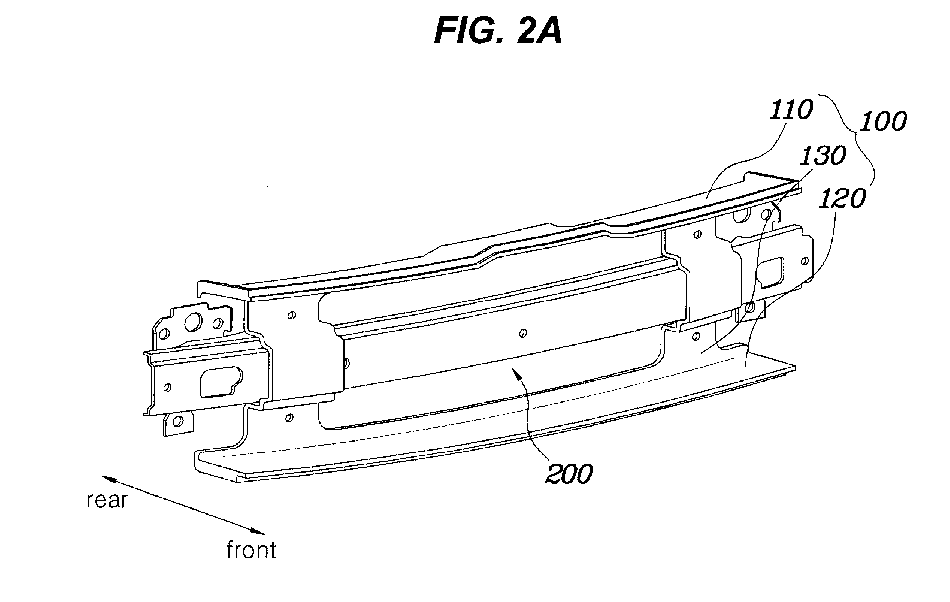
As is apparent from the above description, a stiffener for a vehicle according to the present invention is advantageous in that the stiffener protrudes from the upper and lower portions of a bumper back beam, so that the upper and lower parts of the stiffener complementarily move in a seesaw type manner to absorb shocks in the event of a collision between a vehicle and a pedestrian, thus decreasing the extent of injury to a pedestrian.
Further, a stiffener for a vehicle according to the present invention is advantageous in that the stiffener protruding from the upper and lower portions of a bumper back beam has an integrated structure, so that manufacturing cost and weight thereof are reduced, and the number of portions which are to be assembled is reduced. As such, the stiffener is advantageous in terms of processing.
Further, a stiffener for a vehicle according to the present invention is advantageous in that it is made of a glass mat reinforced thermoplastics (GMT) material and has a plate-shaped section, so that it is possible to attain a stable evaluation score in a collision test, and performance satisfying regulations concerning marketability is achieved.

Problems solved by technology

However, the conventional stiffener is problematic in that pressure generated by a vehicle collision is concentrated on a portion under a pedestrian's knee, so that his or her injury is increased.

Method used


Image

  • Stiffener for Vehicle
  • Stiffener for Vehicle
  • Stiffener for Vehicle

Examples


Embodiment Construction

Reference will now be made in detail to various embodiments of the present invention(s), examples of which are illustrated in the accompanying drawings and described below. While the invention(s) will be described in conjunction with exemplary embodiments, it will be understood that present description is not intended to limit the invention(s) to those exemplary embodiments. On the contrary, the invention(s) is / are intended to cover not only the exemplary embodiments, but also various alternatives, modifications, equivalents and other embodiments, which may be included within the spirit and scope of the invention as defined by the appended claims.

Hereinafter, a stiffener for a vehicle according to an embodiment of the present invention will be described in detail with reference to the accompanying drawings.

As shown in FIGS. 1 to 3, a stiffener 100 according to an exemplary embodiment of the present invention is constructed so that an upper stiffener part 110 and a lower stiffener pa...


PUM


Abstract

A stiffener for a vehicle, may include a coupling stiffener part, an upper stiffener part extending integrally from an upper end of the coupling stiffener part, and protruding to a forward direction of the vehicle with a predetermined length, and a lower stiffener part extending integrally from a lower end of the coupling stiffener part, and protruding to the forward direction of the vehicle, with a predetermined length, wherein the coupling stiffener is secured to a bumper back beam, and wherein the upper stiffener part and the lower stiffener part are complementarily operated about the coupling stiffener part serving as a support shaft in a seesaw type manner to absorb shocks, in the event of a collision between the vehicle and a pedestrian.

Description

The present application claims priority to Korean Patent Application No. 10-2009-0115819, filed on Nov. 27, 2009, the entire contents of which is incorporated herein for all purposes by this reference.BACKGROUND OF THE INVENTION1. Field of the InventionThe present invention relates generally to a stiffener for a vehicle and, more particularly, to a stiffener for a vehicle, which is constructed so that an upper stiffener part and a lower stiffener part are integrated with each other, thus absorbing shocks at upper and lower parts in the event of a collision between a vehicle and a pedestrian.2. Description of Related ArtGenerally, a back beam is coupled to a carrier of a vehicle to mount a bumper, and a stiffener is mounted to a lower member of the carrier so as to prevent a portion under a pedestrian's knee from entering under a vehicle.As shown in FIG. 4, a back beam 20 is provided on the central portion of a carrier 10 so that a bumper is mounted to the back beam 20, and is couple...

Claims


Application Information

Patent Timeline
Patent Type & Authority Applications(United States)
IPC IPC(8): B60R19/26
CPCB60R19/12B60R19/18B60R2021/343B60R2019/1853B60R2019/186B60R2019/1833B60R19/023B60R21/34B60R2019/1893B60R2021/346B62D21/152
Inventor LEE, JEONG HO
Owner HYUNDAI MOTOR CO LTD
Learn More