Piezoelectric generator and method

a technology of piezoelectric generator and generator module, which is applied in piezoelectric/electrostrictive/magnetostrictive devices, piezoelectric/electrostriction/magnetostriction machines, electrical equipment, etc., can solve the problems of limiting the operation of piezoelectric devices, limiting the use of piezoelectric devices as practical power sources for generating a useful amount of electricity, and limiting the use of piezoelectric devices. to very low power

Active Publication Date: 2011-06-02
UNITED STATES OF AMERICA
View PDF5 Cites 41 Cited by
  • Summary
  • Abstract
  • Description
  • Claims
  • Application Information

AI Technical Summary

Benefits of technology

[0022]The method may comprise mounting stops throughout the array of cymbal transducers to prevent over compression of the array of cymbal transducers.

Problems solved by technology

While piezoelectric materials have been successfully utilized in sensors and actuators, their use as practical power sources for generating a useful amount of electricity in portable generators has been limited.
Users of piezoelectric devices are presently substantially limited to operating only very low power devices, such as LEDs.
This operation is typically limited to only a brief flash.
The need for a large number of piezoelectric transducers with many interconnections between components such as rectifiers and batteries increases the weight, reduces the robustness, and increases the complexity and difficulty of packaging such devices, especially for purposes such as being carried on a person, device, or object.
The prior art does not address the above problems.
The above cited prior art does not disclose a module system that is optimized to generate electrical energy from mechanical and environmental sources, specifically compressive forces, where an array of cymbal transducers is positioned between two rigid plates that are electrically conductive and are coupled to any of the cymbal transducers that are adjacent thereto.

Method used


Image

  • Piezoelectric generator and method
  • Piezoelectric generator and method
  • Piezoelectric generator and method

Examples


Embodiment Construction

[0037]The present invention may be utilized for harvesting electrical energy from environmental, mechanical, and mechanical compression forces that otherwise could not be used.

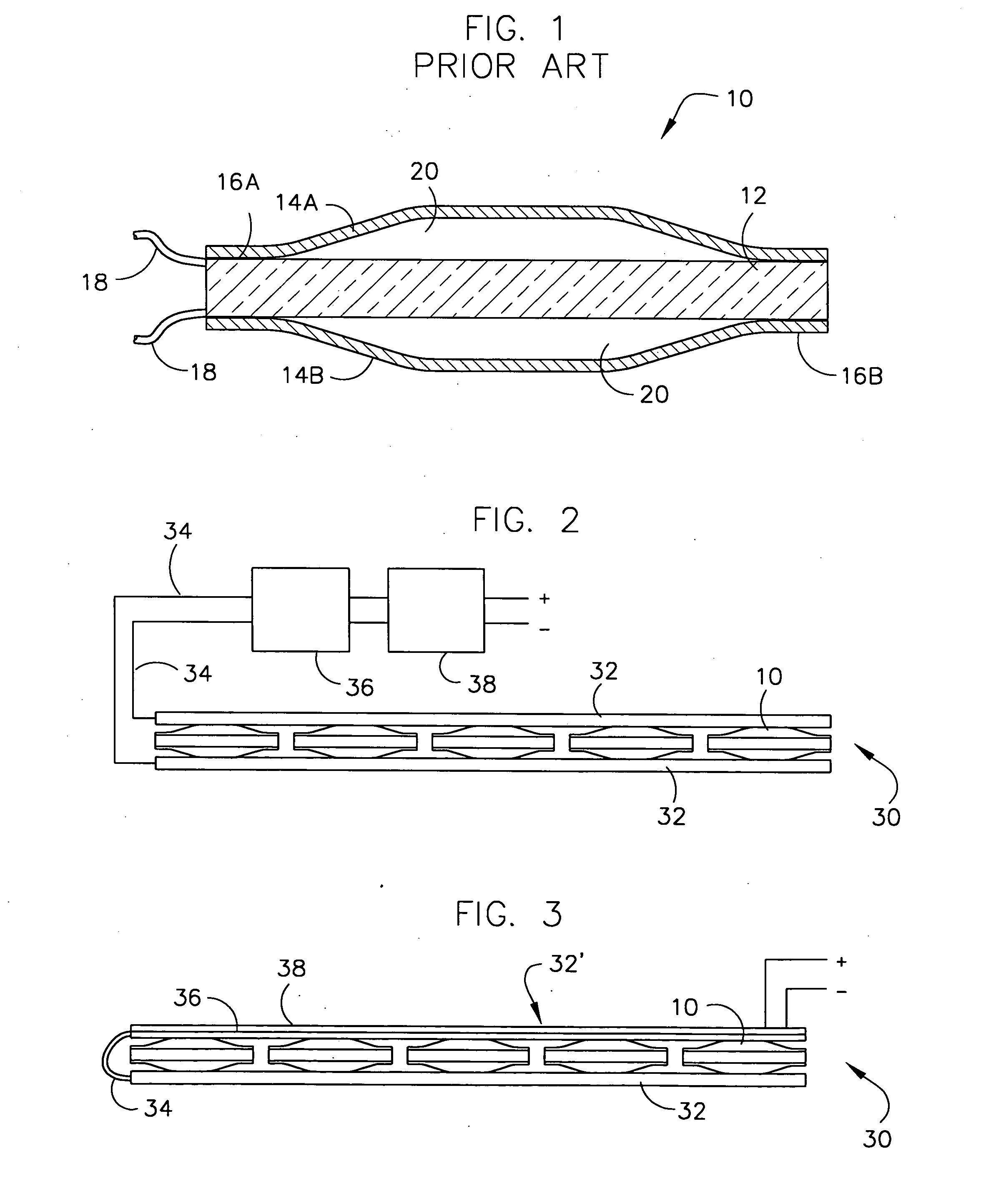
[0038]FIG. 1 illustrates an enlarged view of a type of transducer that is referred to herein as cymbal transducer 10, which may be utilized in accord with the present invention. Transducer 10 has a disk 12 of piezoelectric material. Piezoelectric material can be a single crystal or multi-crystal PZT or the like formed in a disk shape. Cymbals 14A and 14B are joined to top and bottom surfaces 16A and 16B of disk 12. Cymbals 14A and 14B are made from a rigid material that supports elastic deformation. This material can be a metal, a rigid plastic, and / or other suitable material.

[0039]Electrical contacts 18 are joined to each surface of disk 12. If made of metal, cymbals 14A and 14B can provide this electrical contact. However, cymbals 14A and 14B can be used to provide mechanical to support electrical contacts, ...


PUM

PropertyMeasurementUnit
energyaaaaaaaaaa
electrical outputsaaaaaaaaaa
flexibleaaaaaaaaaa

Abstract

An apparatus and method is provided to produce energy from movement of a user. At least one pair of plates is utilized to secure an array of cymbal transducers therebetween. The array of cymbal transducers is electrically interconnected with signal conditioning circuitry and power storage member. Electrical interconnections may comprise parallel and / or series connections between ones or groups of the cymbal transducers.

Description

STATEMENT OF GOVERNMENT INTEREST[0001]The invention described herein may be manufactured and used by or for the Government of the United States of America for governmental purposes without the payment of any royalties thereon or therefore.CROSS REFERENCE TO OTHER PATENT APPLICATIONS[0002]None.BACKGROUND OF THE INVENTION[0003](1) Field of the Invention[0004]The present invention relates generally to electric energy generation from mechanical sources and, more particularly, to a transducer module that is optimized to generate electrical energy from environmental, mechanical, and mechanical compression forces that otherwise could not be used.[0005](2) Description of the Prior Art[0006]While piezoelectric materials have been successfully utilized in sensors and actuators, their use as practical power sources for generating a useful amount of electricity in portable generators has been limited. Users of piezoelectric devices are presently substantially limited to operating only very low ...

Claims


Application Information

Patent Timeline
Patent Type & Authority Applications(United States)
IPC IPC(8): H02N2/18H05K13/00
CPCH01L41/113H02N2/18Y10T29/49002H10N30/30
Inventor HOWARTH, THOMAS R.
Owner UNITED STATES OF AMERICA
Why Eureka
Try Eureka