LED package, LED package module having the same and manufacturing method thereof, and head lamp module having the same and control method thereof

a technology of led package and manufacturing method, which is applied in the direction of solid cathode, gas-filled discharge tube, cathode-ray/electron beam tube circuit elements, etc. it can solve the problems of increased cost and time of manufacturing, increased unnecessary module size, and inability to apply leds to high-level heat radiation characteristics. , to achieve the effect of improving heat radiation efficiency of heat radiation units and reducing cost and time for manufacturing

Inactive Publication Date: 2011-06-02
SAMSUNG ELECTRONICS CO LTD
View PDF17 Cites 87 Cited by
  • Summary
  • Abstract
  • Description
  • Claims
  • Application Information

AI Technical Summary

Benefits of technology

[0011]The present invention has been proposed in order to overcome the above-described problems and it is, therefore, an object of the present invention to provide an LED package in which it is possible to improve heat radiation efficiency of a heat radiation unit i

Problems solved by technology

Therefore, it is impossible to apply the LEDs to a high-power head lamp required for high-level heat radiation characteristics.
However, the use of the wire additionall

Method used


Image

  • LED package, LED package module having the same and manufacturing method thereof, and head lamp module having the same and control method thereof
  • LED package, LED package module having the same and manufacturing method thereof, and head lamp module having the same and control method thereof
  • LED package, LED package module having the same and manufacturing method thereof, and head lamp module having the same and control method thereof

Examples


first embodiment

[0060]First, a description will be given of an LED package module 100 of a first embodiment in accordance with one aspect of the present invention, with reference to FIGS. 1 to 8.

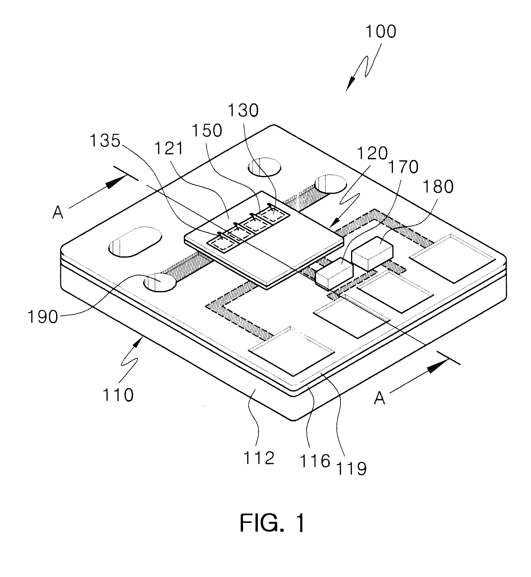
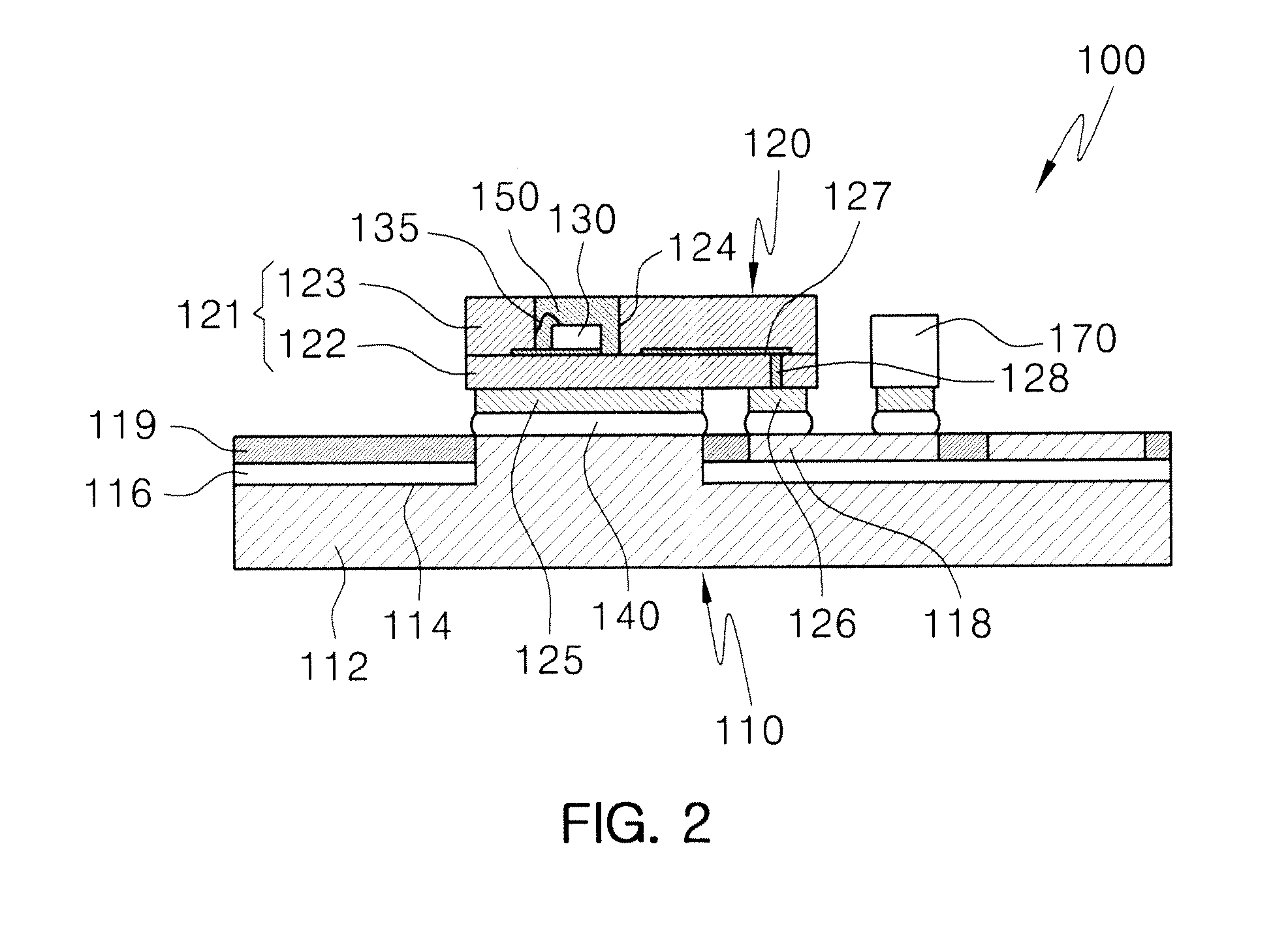
[0061]FIG. 1 is a perspective view showing the LED package module 100 of a first embodiment in accordance with one aspect of the present invention. FIG. 2 is a cross-sectional view showing the LED package module 100 taken along the line AA of FIG. 1. FIG. 3 is a top view showing the LED package module 100 of a first embodiment in accordance with one aspect of the present invention.

[0062]According to the first embodiment in accordance with one aspect of the present invention, as shown in FIGS. 1 to 3, the LED package module 100 includes a heat radiation substrate 110, an LED package 120 which is mounted on the heat radiation substrate 110 by a conductive adhesive layer 140, a zener diode 170 and a thermister 180 each of which is mounted on the heat radiation substrate 110, and an alignment mark 190 formed on...

second embodiment

[0090]As used herein, the bonding means not only that two components are coupled to each other through physically direction contact, but also that the components are coupled to each other through other materials interposed therebetween. the present invention has been described taking an example where the conductive adhesive layer 140 is interposed between two components (i.e., between the heat radiation pad 125 and the heat radiation unit 112, and between the electrode pad 126 and the electrode unit 118) in such a manner that the heat radiation pad 125 and the heat radiation unit 112, and the heat radiation unit 112 and the electrode pad 126 are indirectly coupled to one another through the conductive adhesive layer 140, respectively.

[0091]As shown in FIG. 2 and FIGS. 4 and 5, the electrode pad 126 is formed on the package substrate 121 in such a manner to be opposite to and be bonded to the electrode unit 118. A pair of the electrode pads 126 is formed on a lower surface of the pac...


PUM


Abstract

Disclosed are an LED package, an LED package module having the same and a manufacturing method thereof, and a head lamp module having the same and a control method thereof. The light emitting diode package includes: a package substrate; a light emitting diode chip mounted on one surface of the package substrate; an electrode pad formed on the other surface of the package substrate and electrically connected to the light emitting diode chip; and a heat radiation pad formed on the other surface of the package substrate and electrically insulated from the electrode pad.

Description

CROSS-REFERENCE TO RELATED APPLICATIONS[0001]This application claims the benefit of Korean Patent Application No. 10-2009-0116550 filed with the Korea Intellectual Property Office on Nov. 30, 2009, the disclosure of which is incorporated herein by reference.BACKGROUND OF THE INVENTION[0002]1. Field of the Invention[0003]The present invention relates to an LED package, an LED package module having the same and a manufacturing method thereof, and a head lamp module having the same and a control method thereof.[0004]2. Description of the Related Art[0005]With the development of light emitting diodes (hereinafter, referred to as ‘LEDs’), the LEDs are being widely used even in the head lamp of an automobile. A head lamp employing LEDs may include a light source module having LEDs mounted thereon, a lamp optical module for adjusting light generated from the light source module in conformity with the head lamp of an automobile, a driving driver module for driving LEDs, and a heat radiation...

Claims


Application Information

Patent Timeline
IPC IPC(8): H01K1/62H01L33/62H01L33/58H01L33/08F21V11/00
CPCF21S48/1159H01L33/647H05K1/056H05K2201/09054F21V29/89H05K2201/10174H05K2201/10969H01L2224/13F21V29/677H05K2201/10106F21S41/148F21S41/151F21S41/192F21S45/43F21S41/147
Inventor LEE, YOUNG JINKIM, HYUNG KUN
Owner SAMSUNG ELECTRONICS CO LTD
Why Eureka
Try Eureka