Multi-channel magnetic resonance imaging and spectroscopy

a multi-channel magnetic resonance and imaging technology, applied in the field of magnetic resonance imaging and spectroscopy, can solve the problem that the technique of adjusting the excitation uniformity of the rf coil array is limited, and achieves the effect of improving the uniformity of excitation of the rf coil array

Active Publication Date: 2011-06-02
KONINKLIJKE PHILIPS ELECTRONICS NV
View PDF14 Cites 18 Cited by
  • Summary
  • Abstract
  • Description
  • Claims
  • Application Information

AI Technical Summary

Benefits of technology

The patent describes an improved method for adjusting the excitation of multiple RF coils in an MR system to ensure uniformity of the RF pulse sequence. This is achieved by applying the excitation pulses in two different patterns, one for the preparation segment and another for the acquisition segment. The method compensates for non-uniformities caused by the subject being examined and the frequency of operation of the RF coils. The MR system also includes a control unit to activate the RF coils in the first or second pattern, depending on the physiological state of the subject. The computer program enables the control unit to activate the RF coils in a first pattern for the preparation segment and in a second pattern for the acquisition segment. The technical effects of the patent are improved RF pulse sequence uniformity and dynamic compensation for changes in the subject's size and shape during an MR examination.

Problems solved by technology

The patent text discusses a technique for selecting the best coil for magnetic resonance imaging (MRI) based on an index gauge. However, this technique does not allow for adjusting the excitation uniformity of the coil array based on the patient's physiological phase, such as respiratory or cardiac. The technical problem addressed in this patent is to improve the ability of an RF coil array to adjust its excitation uniformity based on the patient's physiological phase. This would lead to better image quality and reduced artifacts. Additionally, this patent aims to provide an MR system and computer program that can utilize this improved RF coil array.

Method used


Image

  • Multi-channel magnetic resonance imaging and spectroscopy
  • Multi-channel magnetic resonance imaging and spectroscopy
  • Multi-channel magnetic resonance imaging and spectroscopy

Examples


Embodiment Construction

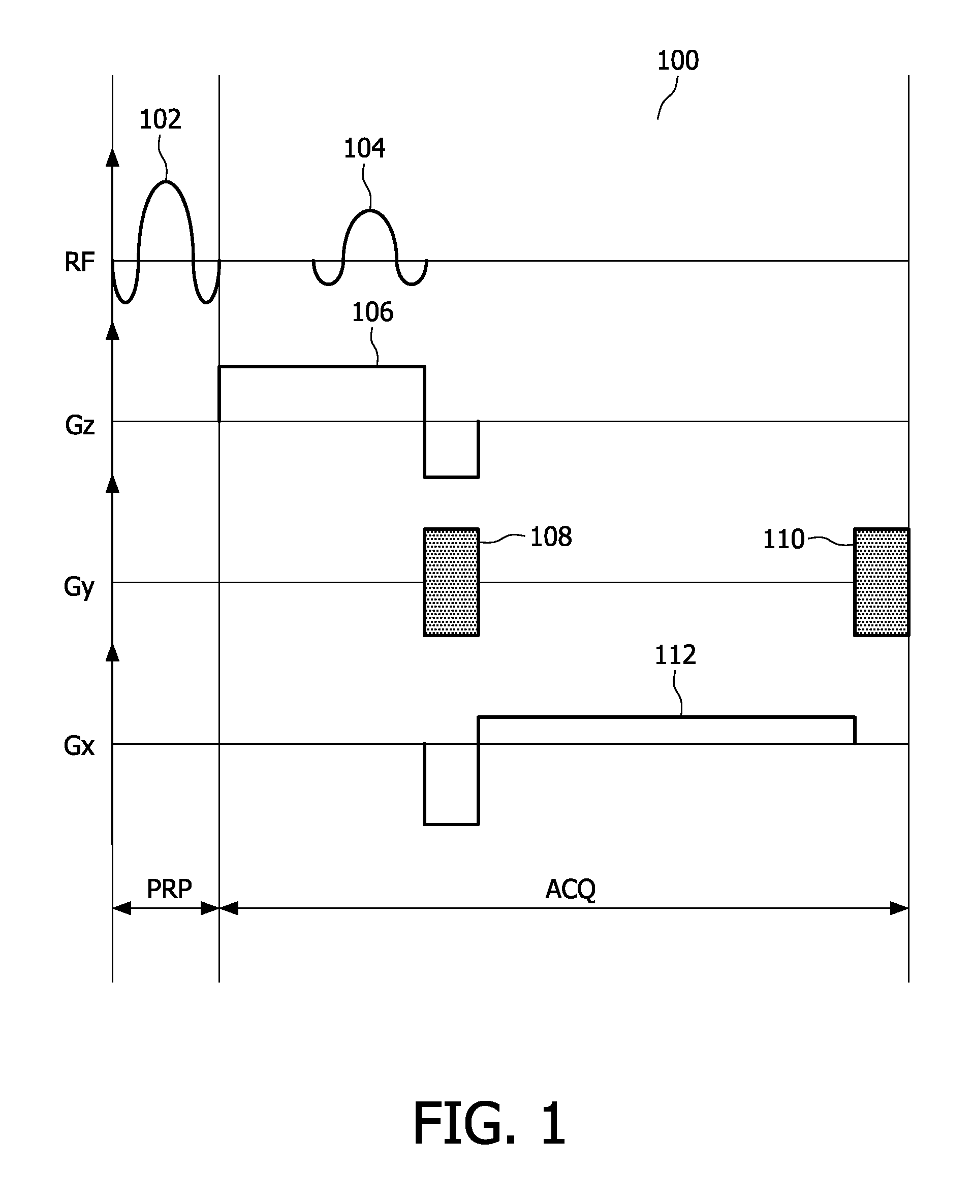
[0012]FIG. 1 is a diagrammatic representation of an MR pulse sequence 100, also called a pulse sequence timing diagram, showing the time sequence of application of various pulses. For example, the line labelled RF represents the application of RF pulses 102, 104, while the lines labelled Gz, Gy and Gx represent gradient pulses applied along the z, y and x-directions, respectively. Specifically, the pulse sequence 100 shown in FIG. 1 shows a slice-select gradient 106 being applied along the z-direction, a phase-encoding gradient 108 and a phase-rewinder gradient 110 being applied along the y-direction and a readout gradient 12 being applied along the x-direction. The entire pulse sequence 100 is divided into two segments, a preparation segment PRP and an acquisition segment ACQ. In the particular case shown, the preparation segment PRP comprises only a single RF pulse 102, and the acquisition segment ACQ comprises the imaging sequence consisting of the RF excitation pulse 104 and its...


PUM


Abstract

A magnetic resonance (MR) system comprising multiple radio-frequency (RP) coils (303) configured to apply an MR pulse sequence (100) including at least a preparation segment (PRP) and an acquisition segment (ACQ), wherein the preparation segment (PRP) and the acquisition segment (ACQ) each comprise one or more excitation pulses, is disclosed herein. The MR system further comprises a first control unit (308) configured to apply the one or more excitation pulses of the preparation segment (PRP) by activating the multiple radio-frequency coils in a first excitation pattern, and a second control unit configured to apply the one or more excitation pulses of the acquisition segment (ACQ) by activating the multiple radio-frequency coils in a second excitation pattern, thereby providing dynamic rf shimming.

Description


Claims


Application Information

Patent Timeline
Owner KONINKLIJKE PHILIPS ELECTRONICS NV
Why Eureka
Try Eureka