Transflective display device

a display device and display technology, applied in the field of display devices, can solve the problems of poor ambient contrast ratio and aperture ratio of the transflective display device in the patent, difficult to produce clear images against ambient light, and relatively weak reflectivity of the liquid crystal display structure, etc., to achieve the effect of saving power and high ambient contrast ratio (a-cr)

Inactive Publication Date: 2011-06-02
NAT TAIWAN UNIV
View PDF14 Cites 34 Cited by
  • Summary
  • Abstract
  • Description
  • Claims
  • Application Information

AI Technical Summary

Benefits of technology

[0008]Therefore, an object of the present invention is to provide a transfl...

Problems solved by technology

However, when the ambient condition is dark (for example, dark indoor environment), the reflective light from the liquid crystal display structures is relatively weak.
When the ambient condition is bright (for example, daylight environment), the light emitted from the emissive disp...

Method used


Image

  • Transflective display device
  • Transflective display device
  • Transflective display device

Examples


first embodiment

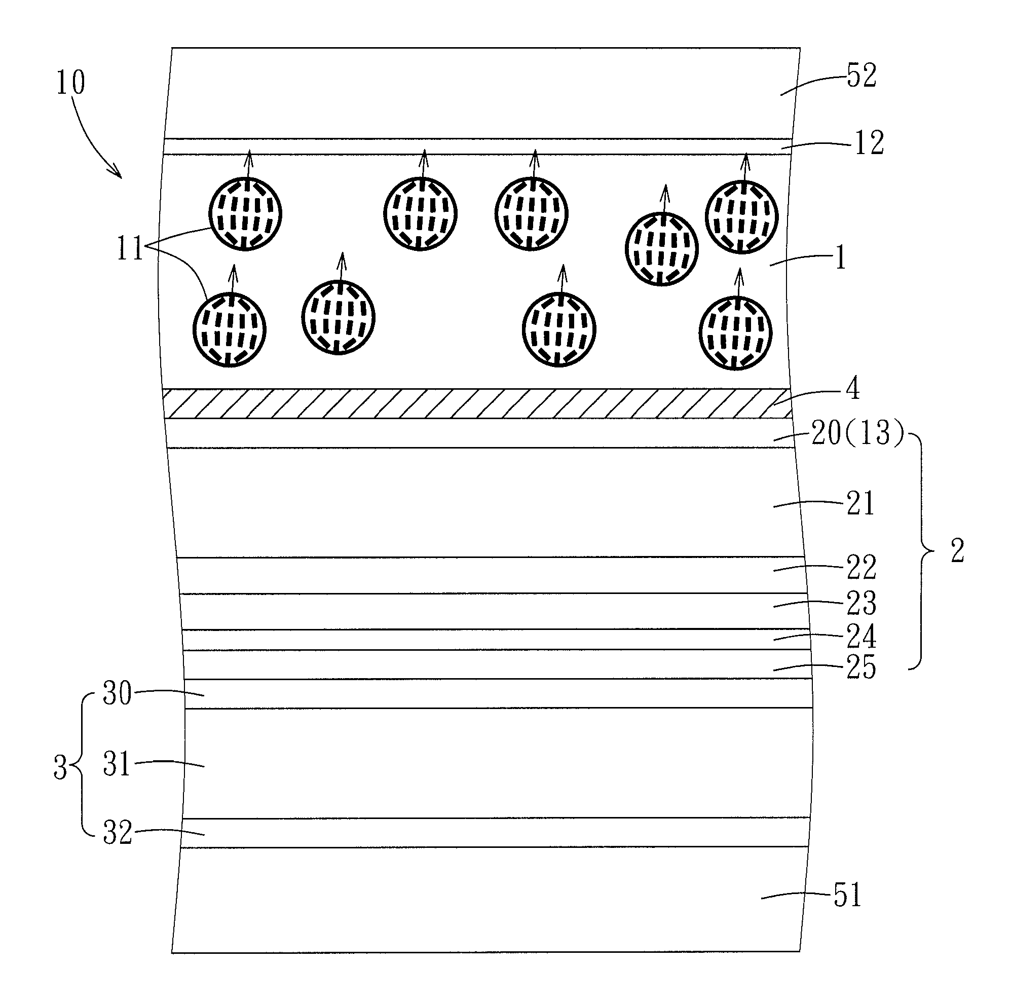
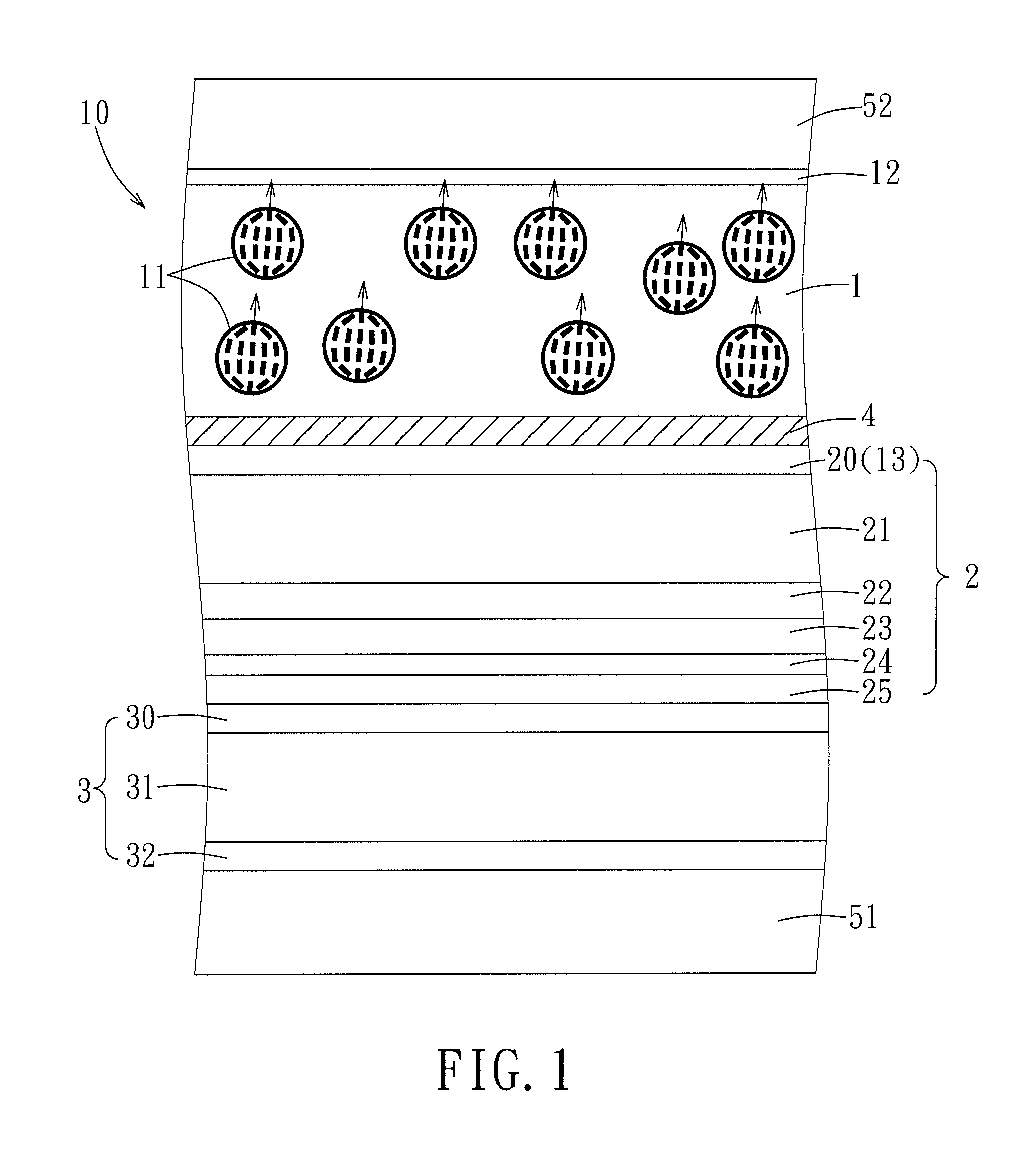
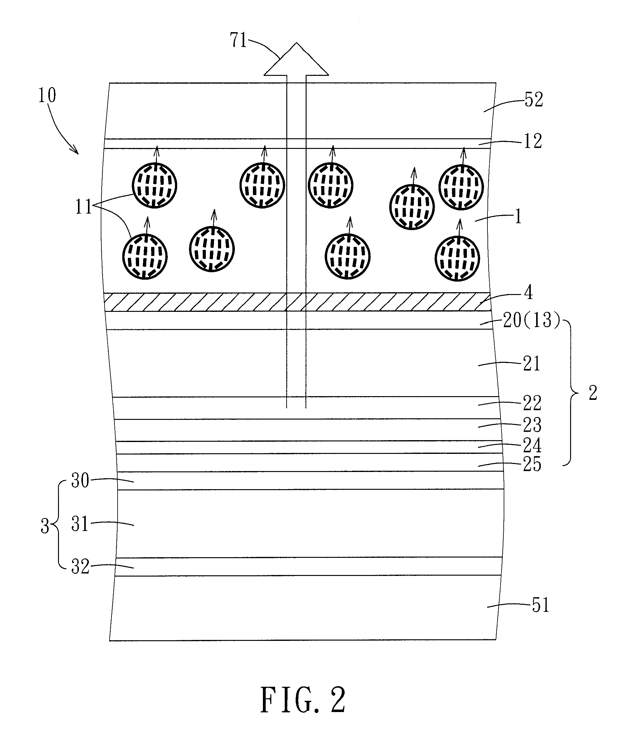
[0027]Referring to FIGS. 1 to 4, a transflective display device according to the present invention comprises lower and upper substrates 51 and 52, and a plurality of pixel regions 10 (only one is shown) between the lower and upper substrates 51, 52.

[0028]The lower and upper substrates 51 and 52 are made of a light-transmissive material, for example, quartz, glass, fibers, semiconductor materials, polymers, etc., based on the actual requirement of the transflective display device.

[0029]Each of the pixel regions 10 is a pixel or a subpixel based on the design of the transflective display device. For the sake of simplicity, only one pixel region 10 is described below.

[0030]The pixel region 10 is controllable to operate at a bright state (ON state) as shown in FIGS. 2 and 4 and a dark state (OFF state) as shown in FIGS. 1 and 3. Furthermore, the pixel region 10 can generate an electrical power by itself using photoelectric effect, and the details thereof are described as follows.

[0031]E...

third embodiment

[0055]Besides, in order to further increase the ambient contrast ratio (A-CR), the liquid crystal display structures 1 and the emissive display structures 2 of the third embodiment can both work for displaying the image, regardless of whether the ambient condition is dark or bright.

[0056]FIG. 7 illustrates a pixel region 10 of a transflective display device according to the fourth embodiment of the present invention. The fourth embodiment differs from the third embodiment only in that the layers 20 to 25 and the layers 30 to 32 are arranged in a different order. In this embodiment, the emissive display structure 2 includes, from top to bottom, a first cathode layer 25, an electron injection layer 24, an electron transport layer 23, an light emitting layer 22, a hole transport layer 21 and a first anode layer 20. The photovoltaic structure 3 includes, from top to bottom, a second cathode layer 30, a photovoltaic layer 31, and a second anode layer 32.

[0057]Moreover, the photovoltaic s...


PUM

PropertyMeasurementUnit
Poweraaaaaaaaaa
Brightnessaaaaaaaaaa
Reflectionaaaaaaaaaa

Abstract

A transflective display device includes upper and lower substrates, and a plurality of pixel regions that are disposed between the upper and lower substrates. Each of the pixel regions is controllable to switch between a bright state and a dark state, and includes a liquid crystal display structure, an emissive display structure, and a photovoltaic structure. The photovoltaic structure is capable of absorbing light to generate an electrical power. The liquid crystal display structure is controllable to operate between a transmissive mode and a reflective mode. The emissive display structure is controllable to emit graded light or to not emit light.

Description

CROSS-REFERENCE TO RELATED APPLICATION[0001]This application claims priority of Taiwanese application no. 098140595, filed on Nov. 27, 2009.BACKGROUND OF THE INVENTION[0002]1. Field of the Invention[0003]This invention relates to a display device, more particularly to a transflective display device.[0004]2. Description of the Related Art[0005]Transflective display devices provide improved visibility in bright and dark ambient conditions. Typically, a transflective display device includes a plurality of pixel regions each of which is constituted by a liquid crystal display structure and an emissive display structure. For displaying an image, the liquid crystal display structure in each pixel region is controlled to operate at a reflective mode or a transmissive mode. The emissive display structure in each pixel region is controlled to operate at an emissive state to emit light, or at a non-emissive state to not emit light.[0006]Such kind of the transflective display device is disclos...

Claims


Application Information

Patent Timeline
IPC IPC(8): G09G5/10G09G3/30G09G3/36G02F1/1335G02F1/1334
CPCG02F1/1334G02F2201/44G02F2001/13324G02F1/13324
Inventor LEE, JIUN-HAWCHIU, TIEN-LUNG
Owner NAT TAIWAN UNIV
Why Eureka
Try Eureka