Exposure head and image forming apparatus

a technology of image forming apparatus and head, which is applied in the direction of electrographic process apparatus, printing, instruments, etc., can solve the problems of reducing the amount of lights supplied for spot formation, increasing aberration, and reducing light use efficiency, so as to reduce life span, reduce aberration, and high accuracy

Inactive Publication Date: 2011-06-02
SEIKO EPSON CORP
View PDF3 Cites 4 Cited by
  • Summary
  • Abstract
  • Description
  • Claims
  • Application Information

AI Technical Summary

Benefits of technology

[0006]An advantage of some aspects of the invention is to provide a technology capable of realizing exposure with high accuracy by reducing the aberration of an image forming optical system and sufficiently ensuring the amount of lights supplied for spot formation.

Problems solved by technology

That is, if the magnification in the main scanning direction is large, the aberration is increased.
Meanwhile, if the magnification in the main scanning direction is small, light use efficiency is reduced, so that the amount of lights supplied for spot formation is reduced.
However, these points have not been sufficiently considered in the related art.
However, in the configuration in which the organic EL elements are surrounded by the head substrate made of glass and the sealing member made of glass, it is difficult to promote the heat dissipation from the organic EL element.
Specifically, when the light emitting element array is a bottom emission type organic EL element array, it is difficult to bring a large light amount of the organic EL element.

Method used


Image

  • Exposure head and image forming apparatus
  • Exposure head and image forming apparatus
  • Exposure head and image forming apparatus

Examples


first embodiment

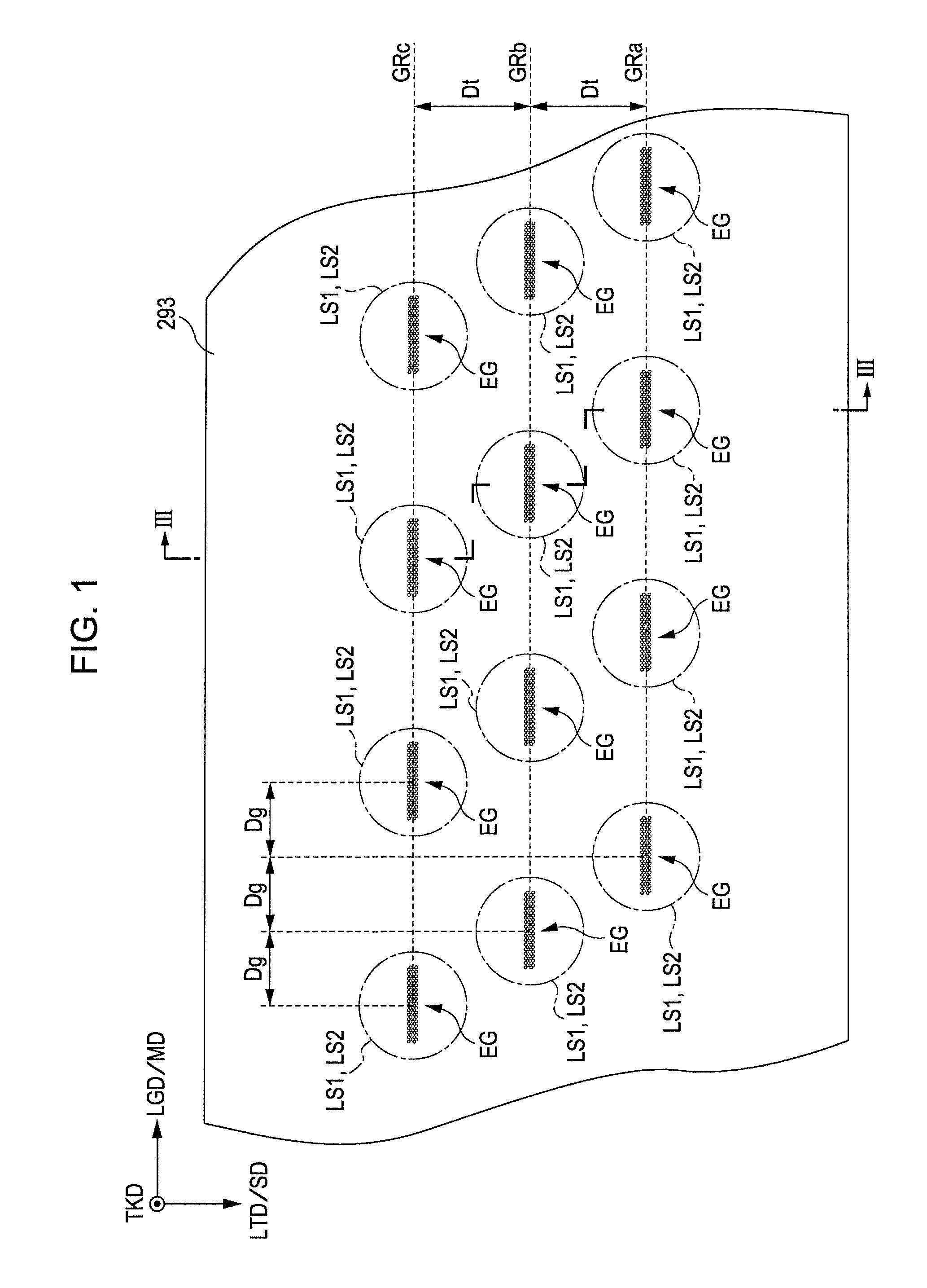
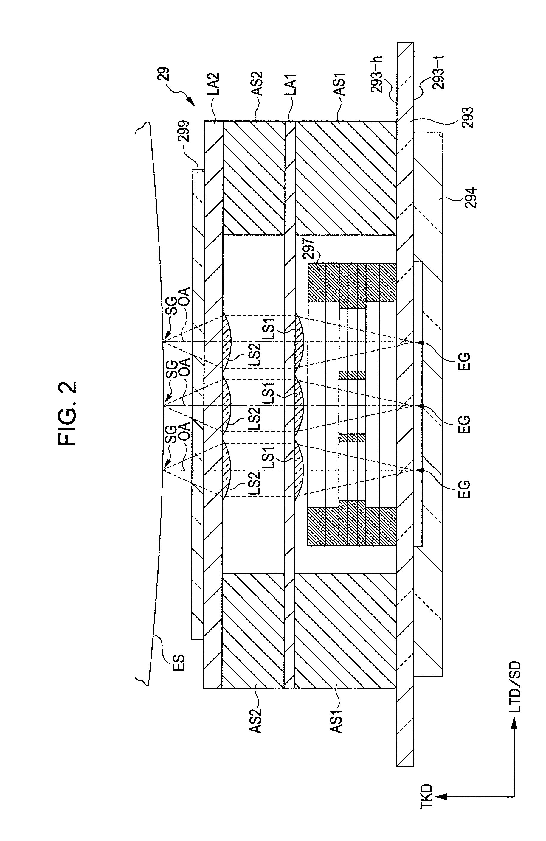
[0048]FIGS. 1 and 2 are diagrams showing one example of a line head to which the present invention can be applied. Specifically, FIG. 1 is a plan view when the positional relationship between light emitting elements and lenses provided in the line head 29 is seen from the thickness direction TKD of the line head 29. FIG. 2 is a partial offset sectional view taken along line I-I (a stepped two-dot chain line of FIG. 1) of the line head 29, which corresponds to when the section is seen from the longitudinal direction LGD of the line head 29. The line head 29 is long in the longitudinal direction LGD while being short in the width direction LTD, and has a predetermined thickness (a height) in the thickness direction TKD. The following drawings including FIGS. 1 and 2 show the longitudinal direction LGD, the width direction LTD, and the thickness direction TKD of the line head 29 if necessary. In addition, these directions LGD, LTD and TKD are perpendicular or substantially perpendicula...

second embodiment

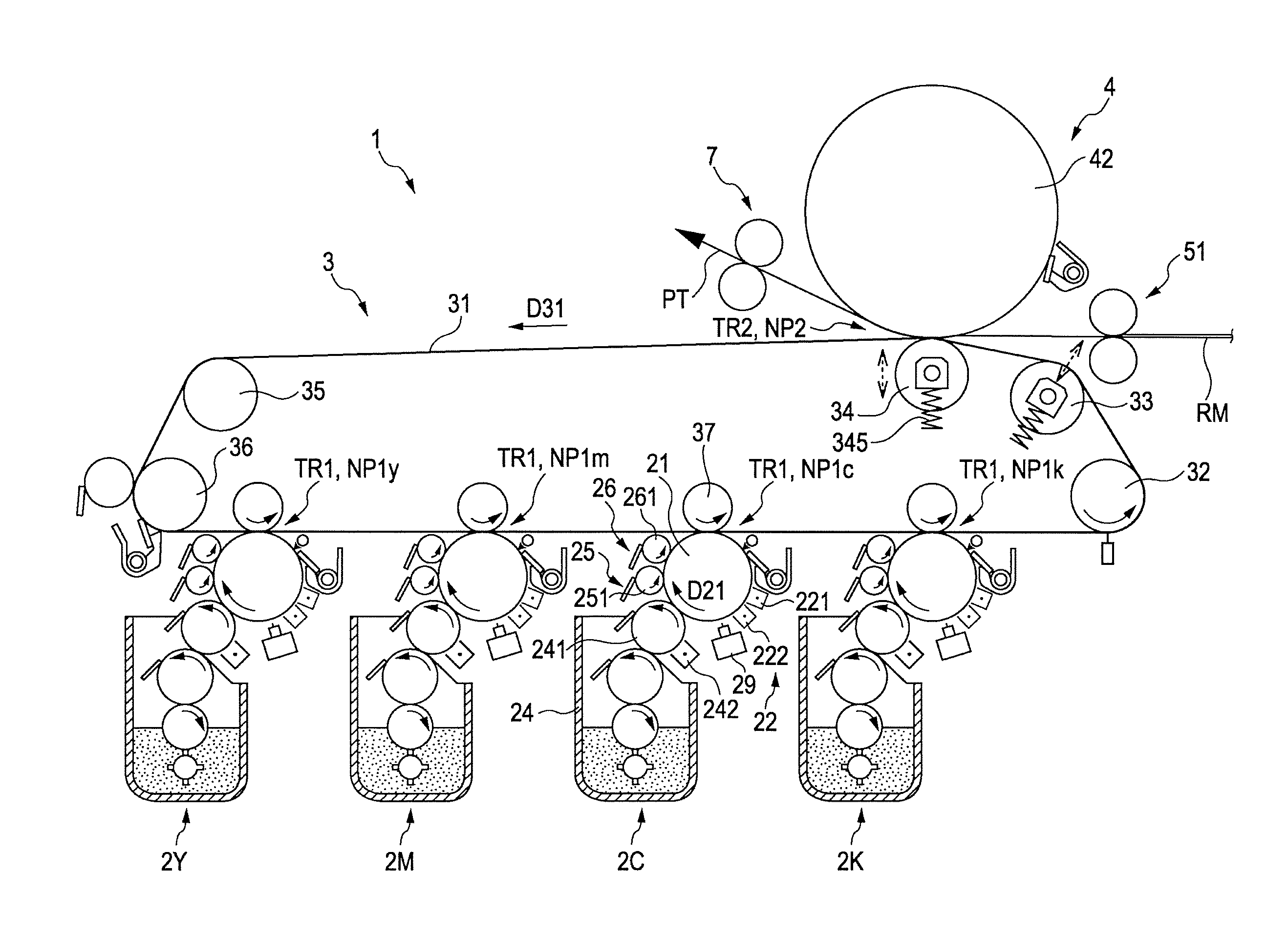
[0090]FIG. 30 is a diagram showing one example of an image forming apparatus to which the above-described line head can be applied. Further, FIG. 31 is a block diagram showing the electrical configuration of the apparatus of FIG. 30. In the second embodiment, one example of the image forming apparatus including the above-described line head 29 will be described with reference to FIGS. 30 and 31. The image forming apparatus 1 includes four image forming stations 2Y (for yellow), 2M (for magenta), 2C (for cyan) and 2K (for black), which form colors different from one another. The image forming apparatus 1 can selectively perform a color mode, in which a color image is formed by superimposing toners of four colors of yellow (Y), magenta (M), cyan (C) and black (K), and a monochrome mode in which a monochrome image is formed using only a toner of black (K).

[0091]In the image forming apparatus, if an image forming command is transmitted from an external apparatus such as a host computer ...


PUM


Abstract

Disclosed is an exposure head including a light emitting element array including light emitting elements disposed in a first direction, a light blocking member including an aperture stop through which lights emitted from the light emitting elements pass, and an image forming optical system that makes an image by using the lights having passed through the light blocking member. An absolute value of a magnification in the first direction of the image forming optical system is equal to or more than 0.7 times and is equal to or less than 0.8 times.

Description

BACKGROUND[0001]1. Technical Field[0002]The present invention relates to an exposure head for making an image by using lights from light emitting elements through an image forming optical system and an image forming apparatus using the same.[0003]2. Related Art[0004]JP-A-2009-098613 discloses an exposure head including a plurality of light emitting elements arranged in a zigzag manner in the main scanning direction, and an image forming optical system facing the plurality of light emitting elements. That is, in the exposure head, by making an image by using a plurality of lights emitted from the light emitting elements through the image forming optical system, spots of the plurality of lights are arranged in the main scanning direction and the plurality of lights are irradiated onto a surface to be exposed. Then, the surface to be exposed is exposed by the spots.[0005]As described above, the exposure head exposes the surface to be exposed by the plurality of spots arranged in the ma...

Claims


Application Information

Patent Timeline
Patent Type & Authority Applications(United States)
IPC IPC(8): H04N1/04
CPCB41J2/451G03G15/0409G03G15/0415G03G15/041G03G2215/0456G03G15/04072G03G15/326
Inventor SOWA, TAKESHIIKUMA, KENKOIZUMI, RYUTAINOUE, NOZOMU
Owner SEIKO EPSON CORP
Why Eureka
Try Eureka