
Method for the acquisition of radionavigation signals carrying spreading code with a quasi-infinite period

a radionavigation signal and quasi-infinite period technology, applied in the field of radionavigation signal acquisition with quasi-infinite period, can solve the problems of sub-carrier spreading waveforms, difficult acquisition and tracking, and the disadvantage of ambiguity of tracking code loop discriminators that exhibit a higher precision given by sub-carriers

Active Publication Date: 2011-06-02
CENT NAT DETUD SPATIALES C N E S
View PDF6 Cites 16 Cited by
  • Summary
  • Abstract
  • Description
  • Claims
  • Application Information

AI Technical Summary

Benefits of technology

[0015]It should be noted that the different segments of code are correlated with the same sequence of samples of the radionavigation signal. As each spreading code sequence corresponds to another search range in the temporal alignment search range between the spreading code and its local replica, then in fact, a plurality of parallel temporal alignment searches is effected in a considerably enlarged global search range, thereby notably reducing the average time for acquiring the radionavigation signal.

Problems solved by technology

However, the sub-carrier spreading waveforms also have some drawbacks, because their acquisition and tracking are more difficult to realise than e.g. the acquisition and tracking of a signal of the BPSK type.
In other words, a tracking code loop discriminator that exhibits a higher precision given by the sub-carrier will have the disadvantage of being ambiguous (in the sense that the delay between the spreading waveform of the received signal and its internal replica is potentially evaluated with respect to an incorrect peak of the correlation function).
If the same strategy is used to acquire signals that carry codes having a long period, then there is a risk of having to wait a considerable time before finding a correlation peak.

Method used


Image

  • Method for the acquisition of radionavigation signals carrying spreading code with a quasi-infinite period
  • Method for the acquisition of radionavigation signals carrying spreading code with a quasi-infinite period
  • Method for the acquisition of radionavigation signals carrying spreading code with a quasi-infinite period

Examples


Embodiment Construction

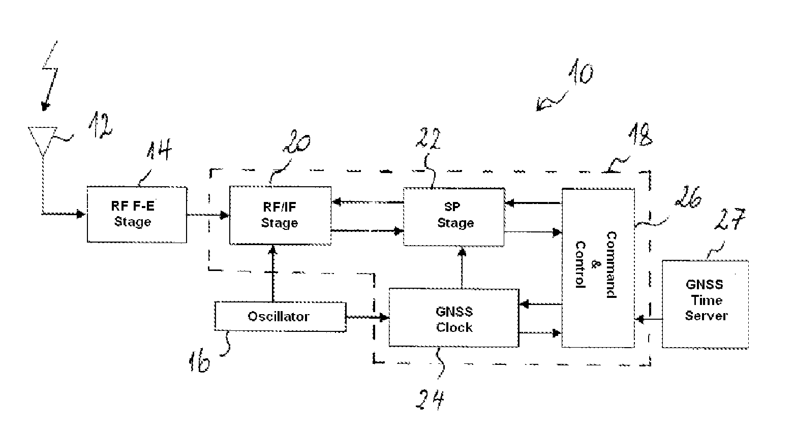
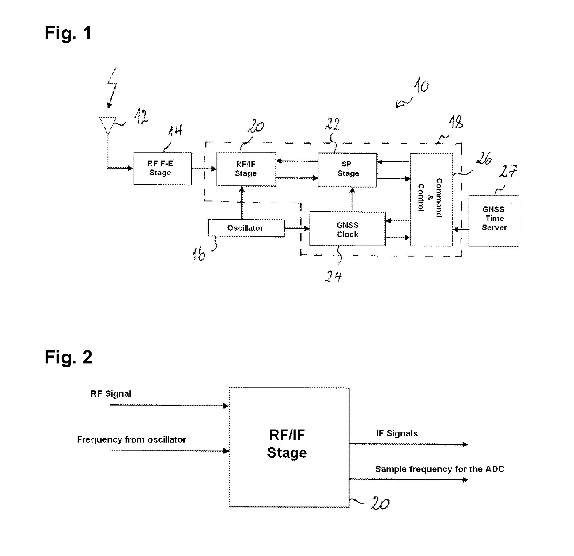
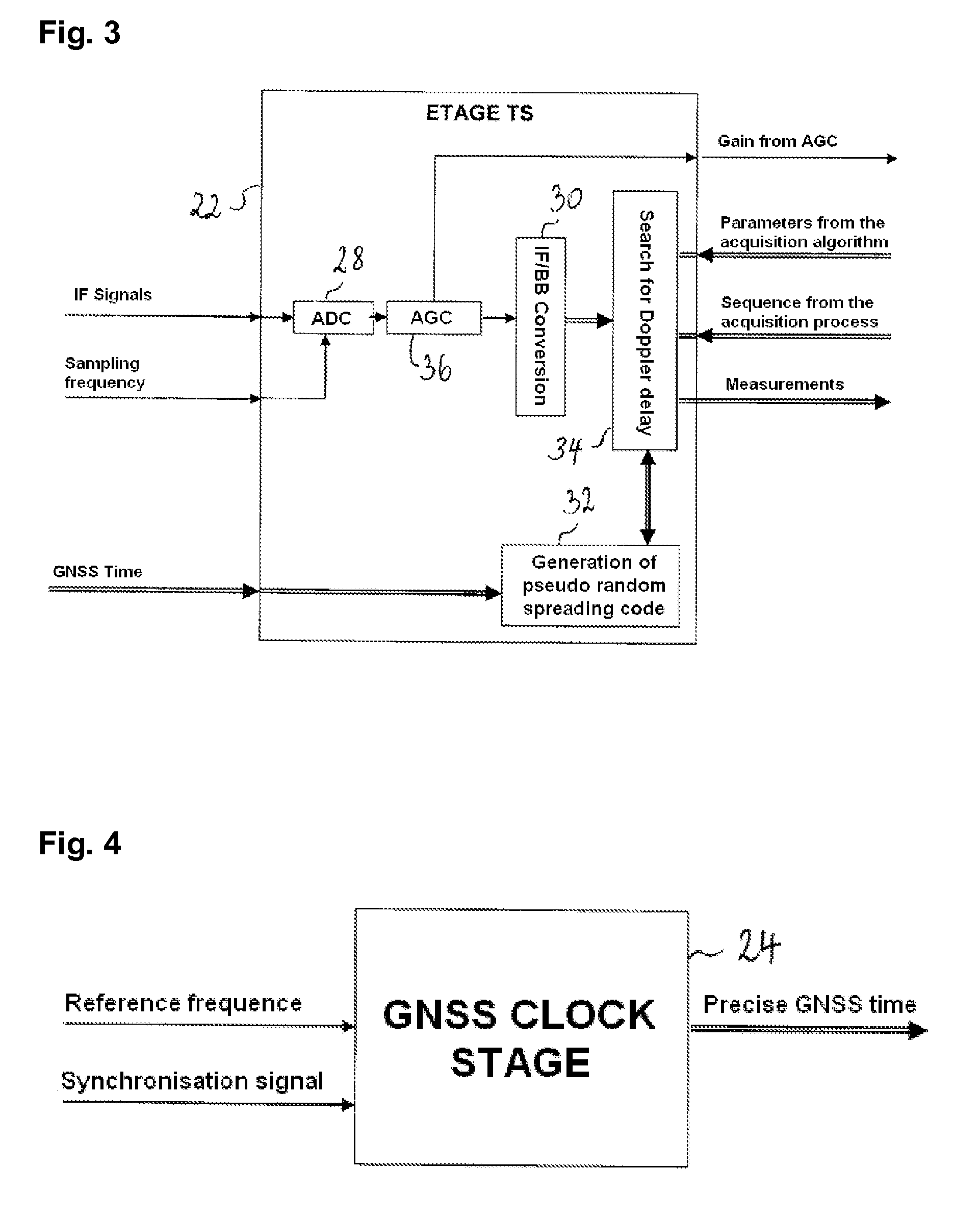
[0032]Un example of an acquisition module for radionavigation signals is shown schematically in FIG. 1 as part of a GNSS receiver. The receiver 10 comprises an antenna 12, a front end radio frequency stage 14, an oscillator 16 as well as the acquisition module 18 that regroups an RF / IF conversion stage 20, a signal treatment stage 22, a clock stage 24 and a command and control stage 26. The acquisition module receives a synchronisation signal from an external time auxiliary, depicted in FIG. 1 as timeserver GNSS 27 (which is not normally part of the GNSS receiver but is linked in communication with it).

[0033]The RF / IF stage 20 is shown in more detail in FIG. 2. It ensures the transposition of the radionavigation signals received in the radio frequency band (RF) towards an intermediate frequency (IF), the generation of the sampling frequency for the analogue to digital converters (ADC) downstream from the signal treatment stage 22, the maintenance of the signal strength about the opt...


PUM


Abstract

A method for the acquisition of a radionavigation signal carrying a spreading code with a quasi-infinite period, where the signal is sampled in baseband on a delay line and correlated with a local spreading code replica, the sampled signal is shifted on the delay line from one correlation to the other, where in order to correlate the signal with the local replica of the code, a plurality of sequences of the spreading code are generated, the code sequences being of the same duration, equal to the duration of the signal sampled on the delay line, and associated with the consecutive time ranges in the temporal alignment search space, where each of the code sequences is correlated with the signal sampled in a respective correlation operation, the correlation operations being executed in parallel for the different sequences of code.

Description

TECHNICAL FIELD[0001]The present invention relates to an acquisition method, preferably assisted in external time, of radionavigation signals carrying spreading codes with a quasi-infinite period. The invention moreover relates to a means for implementing such a process.BACKGROUND[0002]Generally speaking, radionavigation signals transmitted by satellites (or pseudolites) of a positioning system are in the form of a carrier modulated by a type of spreading waveform containing a pseudo-random binary code (“spreading code”). As the modulation of the carrier causes the spreading of the spectrum around the carrier frequency, the radionavigation signals are often called “in spread-spectrum”. The pseudo-random codes represent a signal identifier and therefore an identifier of the transmitting satellite. When known to the receivers, they enable the receivers with a code division multiple access (CDMA). Secondarily, certain satellite positioning signals can also transport useful data (e.g. t...

Claims


Application Information

Patent Timeline
Patent Type & Authority Applications(United States)
IPC IPC(8): H04B1/709
CPCH04B1/708G01S19/30
Inventor DE LATOUR, ANTOINE RICHARD
Owner CENT NAT DETUD SPATIALES C N E S
Learn More