Tensioner

a technology of tensioner and ring, which is applied in the direction of belt/chain/ring, mechanical equipment, belts, etc., can solve the problems of retraction of the ring, and achieve the effect of reducing the sound of the ring and relieving the impa

Active Publication Date: 2011-06-02
BORG WARNER MORSE TEC JAPAN KK
View PDF8 Cites 15 Cited by
  • Summary
  • Abstract
  • Description
  • Claims
  • Application Information

AI Technical Summary

Benefits of technology

[0029]According to the present invention, when the circlip member comes into contact with the rear side stop of the guide groove of the housing at the time of retraction of the piston, the circlip member travels a short distance toward the front side on the piston-retraction restricti

Problems solved by technology

Also, during operation, when tension in the chain increases due to resonance of a chain span, an excessive shock load

Method used


Image

  • Tensioner
  • Tensioner
  • Tensioner

Examples


Embodiment Construction

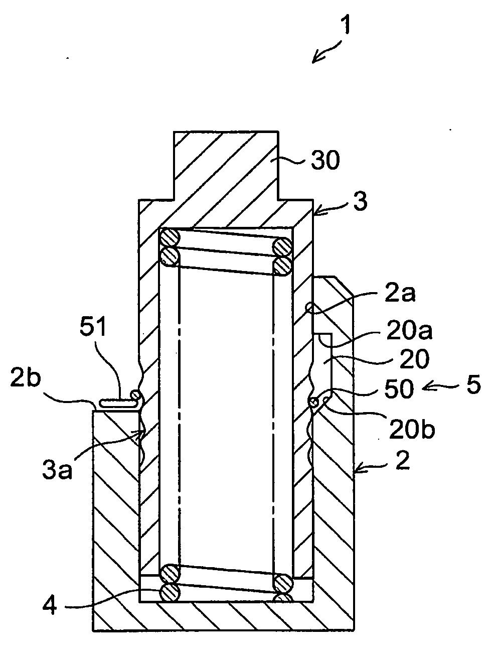
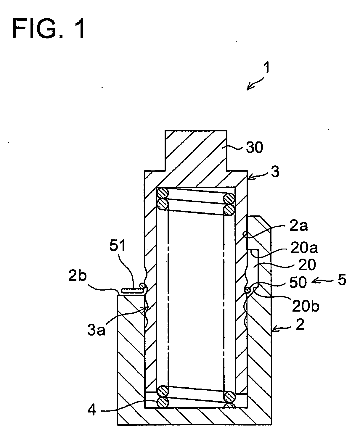
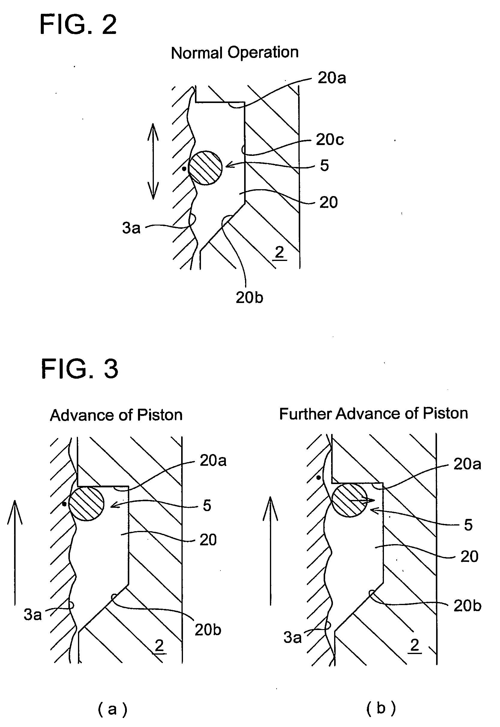
[0041]Embodiments of the present invention will be hereinafter described in accordance with the appended drawings. FIGS. 1 to 6 show a tensioner with a ratchet mechanism according to an embodiment of the present invention. FIG. 1 is a longitudinal sectional view of a tensioner with a ratchet mechanism. FIGS. 2 to 4 illustrate the action of the ratchet mechanism. FIG. 5 is an enlarged view of the engagement groove of the piston and the circlip member. FIG. 6 is a schematic illustrating the action of the ratchet mechanism at the time of restriction of the piston-retraction, corresponding to the enlarged view of a portion of FIG. 4(b).

[0042]As shown in FIG. 1, a tensioner 1 is comprised of a housing 2 having an axially extending piston bore 2a with an opening end and a guide groove 20 formed along the inner circumferential surface of the piston bore 2a at the opening end of the piston bore 2a, a hollow piston 3 slidably supported in the piston bore 2a and having a plurality of engageme...


PUM


Abstract

The present invention is directed to decrease the impact sound of the ratchet mechanism generated at the time of piston retraction. The tensioner includes a piston 3 slidable in the piston bore 2a of the housing 2 and an expandable circlip member 5 engageable with the engagement groove 3a of the piston 3. The piston bore 2a has a guide groove 20 formed therein that has front and rear stop surfaces 20a, 20b adapted to contact the circlip member 5. The engagement groove 3a is formed by a round seat portion S0 that the circlip member 5 is adapted to seat, a piston-retraction restricting portion S0S1 that is formed on front side of the round scat portion S0 and a piston-advance permitting portion S0S2 that is formed on the front side of the round seat portion S0. The piston-retraction restricting portion S0S1 permits the circlip member 5 to travel a short distance toward the front side along the rear side stop surface 20b to allow for an enlargement of the circlip member 5 and to restrict retraction of the piston 3 when the piston 3 retracts and the circlip member 5 contacts the rear side stop surface 20b of the guide groove 20.

Description

TECHNICAL FIELD[0001]The present invention relates to a tensioner with a ratchet mechanism having a circlip member that engages with the engagement grooves formed on the outer circumferential surface of a piston. More particularly, the invention relates to an improvement in the structure of the tensioner to relieve an impact load to decrease impact sound that occurs in the ratchet mechanism when a chain or belt pushes the piston to retract.BACKGROUND ART[0002]Generally, in timing chains in use for valve drives of internal combustion engines, cam shaft chains in use for camshaft-camshaft drives, and balancer chains, tensioners have been used on the slack side of the chain to take up slack in the chain and to apply tension to the chain.[0003]During operation, a piston of the tensioner presses against the chain to maintain tension in the chain. Also, during operation, when tension in the chain increases due to resonance of a chain span, an excessive shock load from the chain acts on th...

Claims


Application Information

Patent Timeline
IPC IPC(8): F16H7/08
CPCF16H7/0848F16H2007/0855F16H2007/0853F16H2007/0806F16H7/08
Inventor BARRETTE, SIMONMIYAKE, KAZUYUKI
Owner BORG WARNER MORSE TEC JAPAN KK
Why Eureka
Try Eureka