Degree of Fraud Calculating Device, Control Method for a Degree of Fraud Calculating Device, and Store Surveillance System

a fraud calculation and control method technology, applied in commerce, instruments, data processing applications, etc., can solve the problems of increasing complexity, fraud activity may go undetected, and the methods used to commit fraud have become more varied and complex, and achieve high reliability

Inactive Publication Date: 2011-06-02
SEIKO EPSON CORP
View PDF8 Cites 32 Cited by
  • Summary
  • Abstract
  • Description
  • Claims
  • Application Information

AI Technical Summary

Benefits of technology

[0008]A degree of fraud calculating device, a control method for a degree of fraud calculating device, and a store surve

Problems solved by technology

This means that some fraudulent activity may go undetected because of the large number of data records that must be checked.
A problem with such systems according to the related art is thus that all instances of fraudulent activity cannot be reliably detected.
The methods used to commit fraud have also become more varied and more complex, and accurately dete

Method used


Image

  • Degree of Fraud Calculating Device, Control Method for a Degree of Fraud Calculating Device, and Store Surveillance System
  • Degree of Fraud Calculating Device, Control Method for a Degree of Fraud Calculating Device, and Store Surveillance System
  • Degree of Fraud Calculating Device, Control Method for a Degree of Fraud Calculating Device, and Store Surveillance System

Examples


embodiment 1

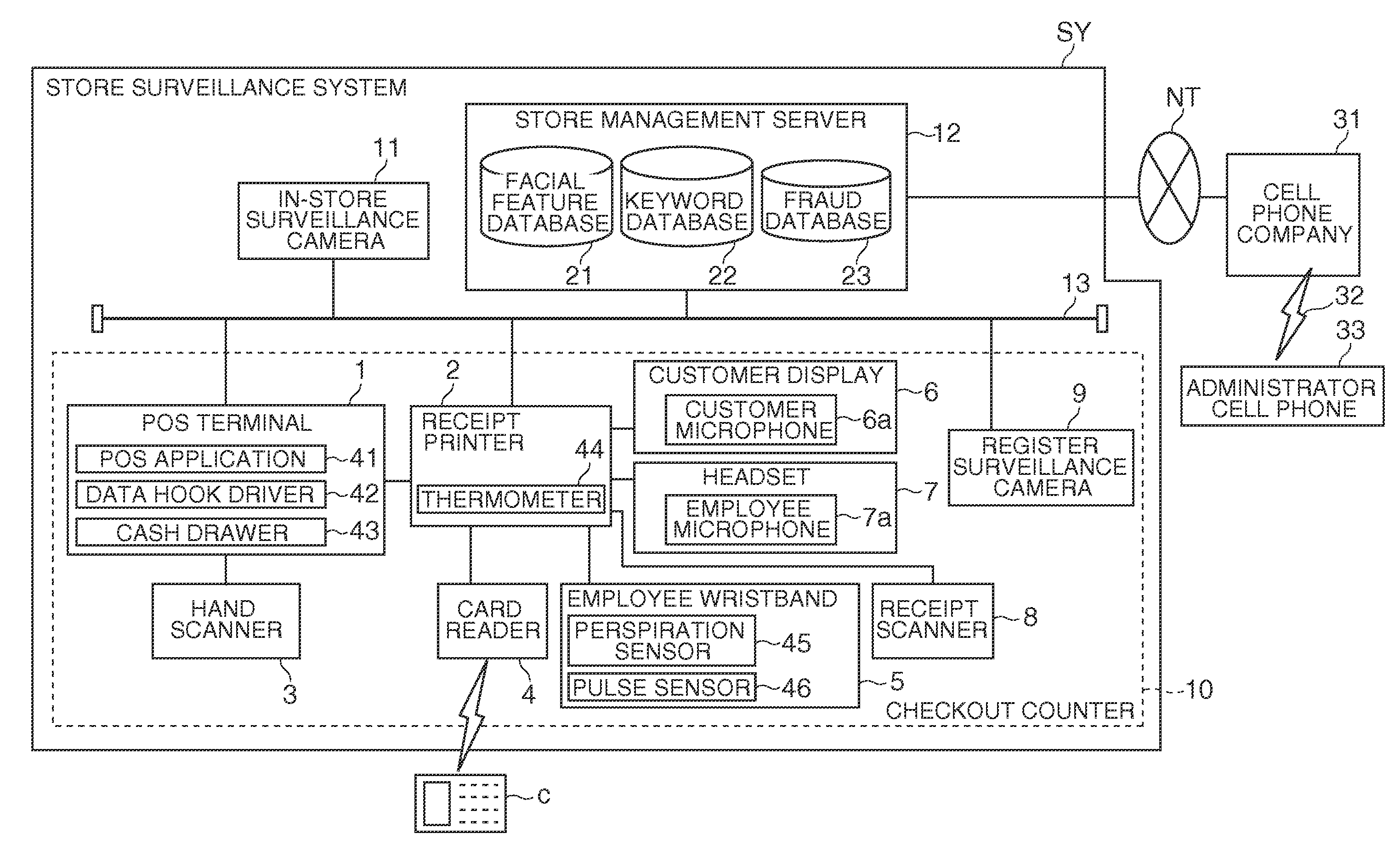
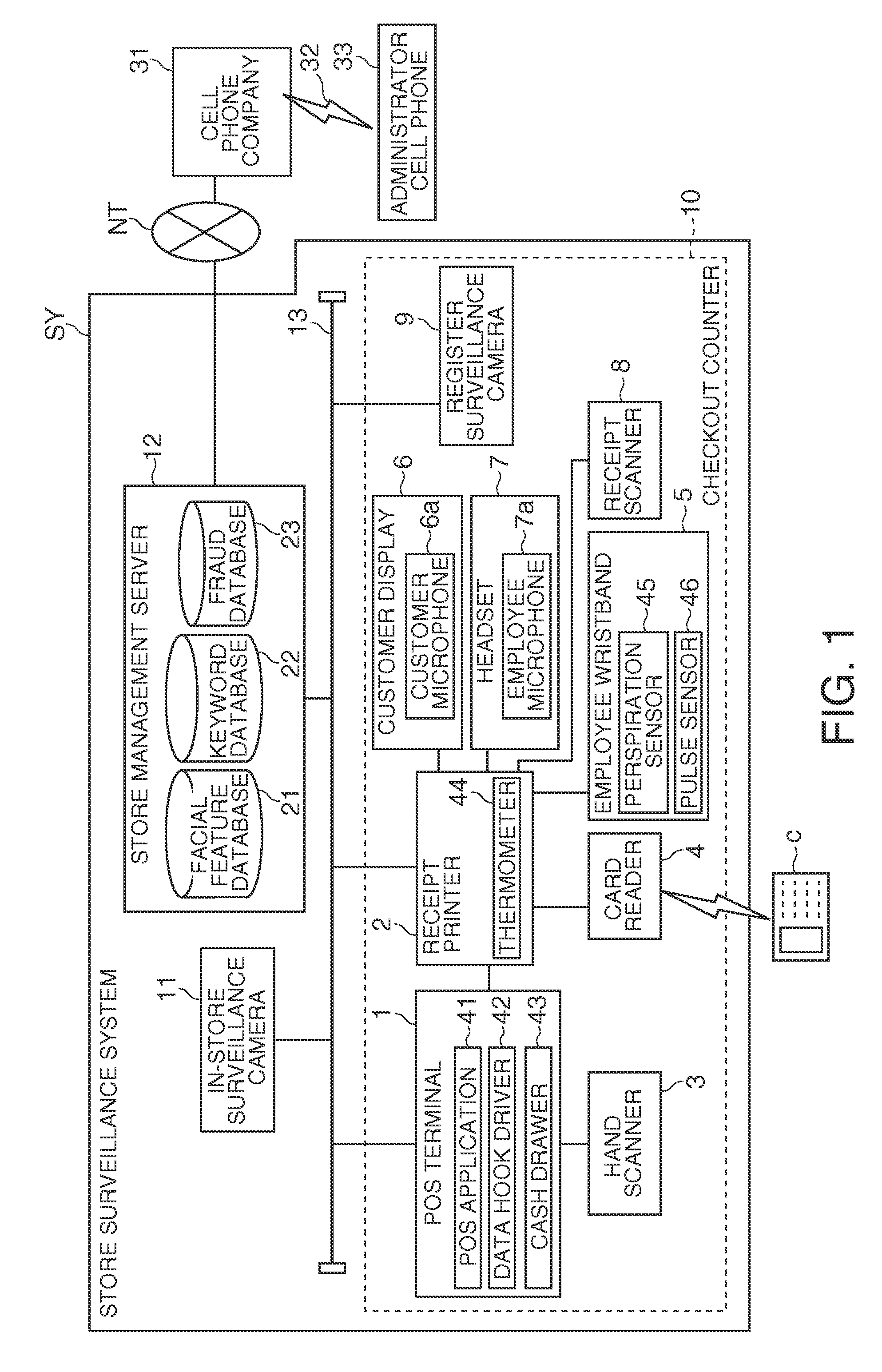
[0052]FIG. 1 is a block diagram of a store surveillance system SY according to the first embodiment of the invention. As shown in FIG. 1, the store surveillance system SY includes a POS terminal 1 that executes a transaction process, a receipt printer 2 that prints receipts (not shown in the figure), a hand scanner 3 that reads barcodes affixed to or printed on products, a card reader 4 that contactlessly reads an employee card C, an employee wristband 5 that is worn on the wrist by the employee (operator), a customer display 6 that displays product information, a headset 7 worn on the head by the employee, a receipt scanner 8 that reads receipts, a register surveillance camera 9 that surveils the checkout counter area, an in-store surveillance camera 11 that monitors the store interior, and a store management server 12 that controls the store surveillance system SY.

[0053]The POS terminal 1 is connected to the receipt printer 2 and hand scanner 3, and the receipt printer 2 is connec...

embodiment 2

[0132]A second embodiment of the invention is described next with reference to FIG. 10 to FIG. 14. This embodiment of the invention is directed to detecting complicated fraudulent activity that occurs in a store and involves a customer as an accomplice. The differences between this and the first embodiment are described below. Note that like parts in this and the first embodiment are identified by like reference numerals, and further description thereof is omitted. In addition, variations involving the same parts as in the first embodiment are also applicable to this embodiment of the invention.

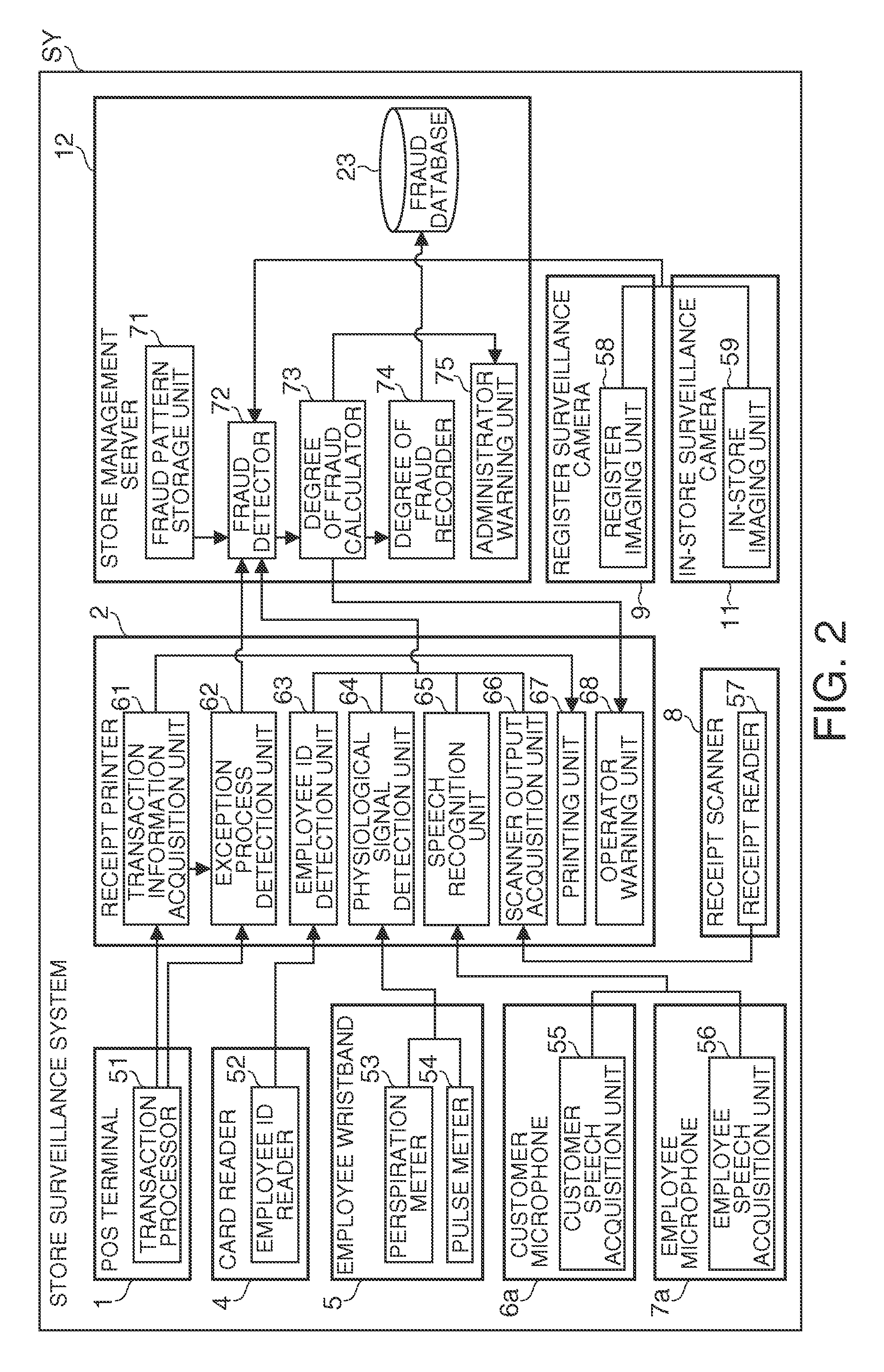
[0133]FIG. 10 is a function block diagram of a store surveillance system SY according to the second embodiment of the invention. The store management server 12 according to this embodiment of the invention differs from that in the first embodiment by the addition of a fraud pattern rewriting unit 76 and a customer detection unit 77.

[0134]The customer detection unit 77 detects a customer durin...


PUM


Abstract

A degree of fraud calculating device, a control method for a degree of fraud calculating device, and a store surveillance system can detect fraudulent activity with a high degree of accuracy. A fraud pattern storage unit 71 that stores a fraud pattern, which sets a basic score that is a weight factor for one or more elements of fraud anticipated in the store; a fraud detection unit 72 that detects if one or more the fraud elements occur; a degree of fraud calculating unit 73 that calculates a degree of fraud by summing the basic scores of the fraud elements detected by the fraud detection unit to have occurred; and a degree of fraud recorder 74 that records the calculated results output by the degree of fraud calculator 73 in a fraud database 23.

Description

CROSS-REFERENCE TO RELATED APPLICATION[0001]Japanese Patent Application No. 2009-274445 filed on Dec. 2, 2009, is hereby incorporated by reference in its entirety.BACKGROUND[0002]1. Technical Field[0003]The present invention relates to a degree of fraud calculating device for detecting fraudulent activity by employees or customers in retail and food service businesses such as supermarkets and restaurants, to a control method for a degree of fraud calculating device, and to a store surveillance system.[0004]2. Related Art[0005]Japanese Unexamined Patent Appl. Pub. JP-A-2005-115504 teaches a system for detecting fraudulent activity by employees during transaction processes in retail stores and the food service industry. The system taught in JP-A-2005-115504 includes a point-of-sale terminal (POS terminal), a camera that images the area around the POS terminal, a photojournal recorder, and a detection terminal. A photojournal recorder stores records containing journal data (transaction...

Claims


Application Information

Patent Timeline
IPC IPC(8): G06Q40/00G06Q30/00
CPCG06Q20/20G06Q30/06G06Q20/209
Inventor AONUMA, MASASHINAKAMURA, JINICHIHAMA, TAKASHIYOSHIZAWA, JUNICHI
Owner SEIKO EPSON CORP
Why Eureka
Try Eureka